Principle of Negative Voltage Generation Circuit Diagram
In electronic circuits, we often need to use negative voltage. For example, when using operational amplifiers, we often need to establish a negative voltage. Below, we will briefly discuss the circuit that converts +5V to -5V as an example.
When negative voltage is required, dedicated negative voltage generation chips are usually chosen, but these chips can be quite expensive, such as the ICL7600, LT1054, etc. I almost forgot the MC34063, which is the most commonly used chip. The negative voltage generation circuit for the 34063 will not be discussed here, as it is available in the datasheet. Below are two commonly used negative voltage generation circuits in microcontroller electronic circuits.
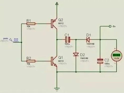
Many modern microcontrollers come with PWM output. When using microcontrollers, PWM is often not utilized, so using it to assist in generating negative voltage is a good choice.
The above circuit is the simplest negative voltage generation circuit. It uses the fewest components and only requires a square wave of about 1kHz, which is quite simple. It should be noted that this circuit has a very weak load capacity, and the voltage drop is also quite large when a load is added.
Due to the above reasons, the following circuit was developed:
Analysis of Negative Voltage Generation Circuit
Definition of Voltage: Voltage (voltage), also known as potential difference or electric potential difference, is a physical quantity that measures the energy difference produced by unit charge in an electric field due to different potentials. Its magnitude is equal to the work done by unit positive charge when moving from point A to point B under the influence of electric field force, and the direction of voltage is defined as pointing from high potential to low potential.
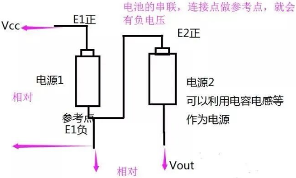
In simple terms: the voltage at a certain point is the difference in potential relative to a reference point. V某 = E某 – E参. Generally, the negative terminal of the power supply is taken as the reference point. The power supply voltage is Vcc = Epower positive – Epower negative.
To generate negative voltage, we need to make its potential lower than that of the power supply’s negative terminal. To achieve a lower potential, another power supply must be involved; the fundamental principle is to use two power supplies in series. The positive terminal of power supply 2 is connected in series with the negative terminal of reference power supply 1, making the negative terminal of power supply 2 the negative voltage.
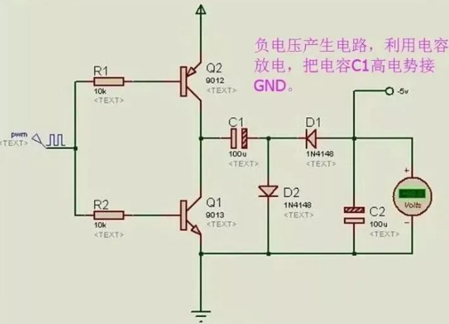
A negative voltage generation circuit: using a capacitor to charge and equivalently create a new power supply, the capacitor is connected in series with GND, thus generating negative voltage.
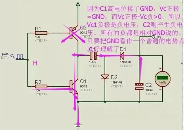
1. Capacitor Charging: When PWM is low, Q2 is turned on, Q1 is turned off, and VCC charges C1 through Q2. The charging loop is VCC – Q2 – C1 – D2 – GND, with C1 having positive on the left and negative on the right.
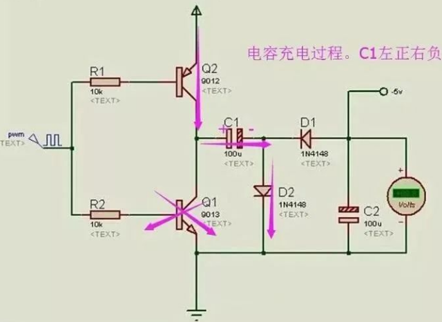
2. Capacitor C1 is fully charged.
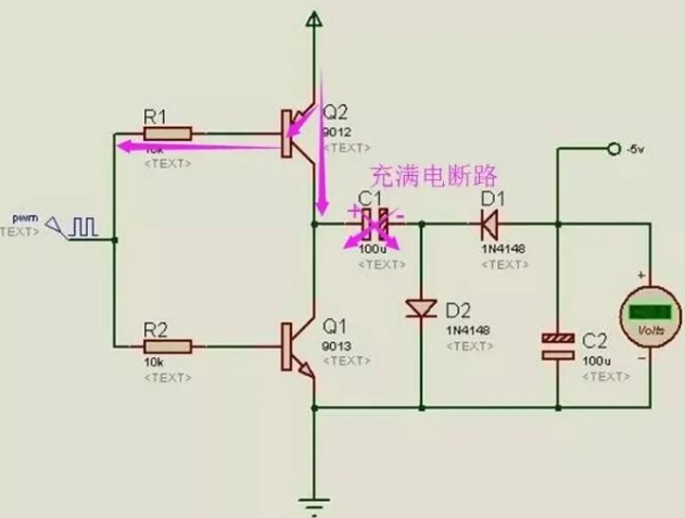
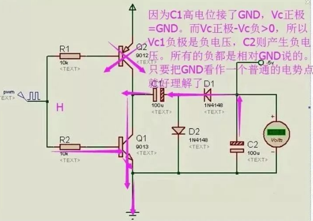
3. Capacitor C1 acts as a power supply, with the high potential end connected in series to the reference point. C1 discharges, continuing the current through C2, generating negative voltage.
When PWM is low, Q2 is turned off, Q1 is turned on, and C1 begins to discharge. The discharge loop is C1 – C2 – D1, which is actually also the process of charging C2. After C2 is fully charged, with the lower terminal positive and the upper terminal negative, if the potential of VCC is around 5 volts, a -5V output can be achieved.
Scheme for generating negative voltage (-5V).
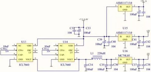
The 7660 and MAX232 have limited output capabilities, making it difficult to drive high-speed operational amplifiers with an oscilloscope, so a parallel configuration of four chips is used to increase current. The first version used two 7660 chips in parallel.Any standard DC/DC chip can generate negative voltage, with voltage accuracy matching that of positive voltage, and strong driving capability, reaching over 300mA.Generally, switching power supply chips can generate negative voltage. If necessary, PWM output from a switching power supply can be used to drive a charge pump, which can also produce significant current at a low cost. The ripple requirement is uncertain; after LC filtering, the ripple of the charge pump is quite small. The 7660 is a charge pump, so the current is very small.The entire oscilloscope design separates the +5V digital power supply from the +5V analog power supply, but how should the digital ground and analog ground be handled?The digital ground and analog ground must be connected together; otherwise, the circuit will not work.The return current of the digital part should not flow through the analog ground; the two grounds should be connected at a stable ground reference point.
Significance of Negative Voltage
-
Man-made Regulation
For example, in telephone systems, -48V is used for power supply to prevent electrochemical corrosion of telephone lines. Of course, connecting the phone in reverse can also work; it just changes the voltage reference point.
-
Communication Interface Requirement
For example, the RS232 interface requires negative voltage. -3V to -15V represents 1, while +3V to +15V represents 0. This was the protocol established when designing the communication interface and must be adhered to. Note: Interface chips like MAX232 come with a charge pump that can generate negative voltage.
-
Power Supply for (Non-Rail-to-Rail) Operational Amplifiers
Older operational amplifiers do not have rail-to-rail input/output capabilities, such as the OP07, where the input voltage range is always less than the power supply voltage range by 1V, and the output is less than 2V. Therefore, if VEE is 0V, the input voltage must exceed 1V, and the output voltage will not be lower than 2V. This may not meet the design requirements of certain circuits. To operate under input/output conditions close to 0V, negative voltage, such as -5V, is needed to allow the operational amplifier to function normally near 0V. However, with the popularity of rail-to-rail operational amplifiers, this situation is becoming less common.
-
Self-Destruct Circuit
Generally, the internal protection circuits of chips are not designed to withstand negative voltage, so even a small current with a not very high negative voltage can successfully destroy the chip.