 Click the blue text to follow, grateful for your support
Welcome friends to follow“Hao Xushua Electronic Design Team“ public account, this public account will regularly update relevant technical materials, software, etc. Friends who are interested can browse other“modules“, hope everyone can gain something they want from this public account“things“.
This article mainlyintroducesthe SPI interface
SPI (Serial Peripheral Interface) is a high-speed, full-duplex, synchronous serial communication bus protocol developed by Motorola (now part of NXP), widely used for short-distance communication between microcontrollers, sensors, memory (such as Flash, SD cards), real-time clocks, touch screens, and other peripheral devices (on the same board or plug-in board).The physical interface (signal lines) of SPIA standard SPI bus uses 4 signal lines: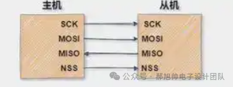 SCLK Serial Clock Output Serial clock generated and output by the master device to all slave devices. Data is sampled on the rising or falling edge of this clock.MOSI Master Out, Slave In Output Master device data output, slave device data input. The master device sends data to the slave device through this line.MISO Master In, Slave Out Input Master device data input, slave device data output. The slave device sends data to the master device through this line.SS/CS Slave Select / Chip Select Output Slave device selection (or chip select). Controlled by the master device to select a specific slave device for communication.In some cases, MOSI and MISO are combined into a bidirectional line, where the host sends or receives data through this line.The SPI interface supports a master-slave mode:
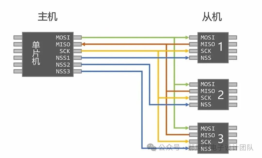 The core features of SPI Synchronous: Communication is driven and synchronized by the clock signal (SCLK) provided by the master device, and all data transmission and reception are based on this clock pulse. This means that the communication parties do not need complex baud rate configurations, and the clock frequency can be very high (up to several tens of MHz).Master-Slave Mode: There must be one (and usually only one) master device in the communication system, responsible for initiating and controlling communication. There can be one or more slave devices.Simple and Efficient: Hardware implementation is simple, software overhead is low, communication efficiency is high, with no start bits, stop bits, or other overhead, making it a true “bit-shifting” protocol.No Flow Control Mechanism: The SPI protocol itself does not define data acknowledgment or flow control mechanisms; these must be ensured by higher-level protocols or applications (determined by specific chips regarding which bits to send first, which bits to send later, and what those bits represent).Working Principle and Data Exchange of SPIInitialization: The master device activates the SS line of the target slave device, indicating the start of communication.Generating Clock: The master device begins to generate the SCLK clock signal.Data Transmission: The master device sends 1 bit of data through the MOSI line. The slave device sends 1 bit of data through the MISO line. Data is sampled and shifted on the clock edge. The specific edge on which it is valid is determined by the clock polarity (CPOL) and clock phase (CPHA).Ending Communication: After data transmission is complete, the master device stops generating SCLK and pulls the SS line high (releases it), indicating the end of communication.Clock Polarity (CPOL) and Clock Phase (CPHA)SPI communication has four different modes, and different slave devices may be configured to a certain mode at the factory. Both parties in communication must operate in the same mode, so we can configure the SPI mode of the master device by controlling the CPOL (clock polarity) and CPHA (clock phase).mode0: CPOL=0, CPHA=0;mode1: CPOL=0, CPHA=1;mode2: CPOL=1, CPHA=0;mode3: CPOL=1, CPHA=1;Clock polarity CPOL is used to configure the state that SCLK should be in when idle;Clock phase CPHA is used to configure at which edge sampling occurs.CPOL=0 indicates that the clock SCLK is low when idle.CPOL=1 indicates that the clock SCLK is high when idle.CPHA=0 indicates that data sampling occurs on the first edge.CPHA=1 indicates that data sampling occurs on the second edge.CPOL=0, CPHA=0: In this case, when idle, SCLK is low, and data sampling occurs on the first edge, which is the transition of SCLK from low to high, so data is sampled on the rising edge, and data is sent on the falling edge.CPOL=0, CPHA=1: In this case, when idle, SCLK is low, and data is sent on the first edge, which is the transition of SCLK from low to high, so data is sampled on the falling edge, and data is sent on the rising edge.CPOL=1, CPHA=0: In this case, when idle, SCLK is high, and data sampling occurs on the first edge, which is the transition of SCLK from high to low, so data is sampled on the falling edge, and data is sent on the rising edge.CPOL=1, CPHA=1: In this case, when idle, SCLK is high, and data is sent on the first edge, which is the transition of SCLK from high to low, so data is sampled on the rising edge, and data is sent on the falling edge.
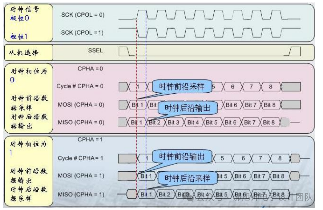 Mode 0 and Mode 3 are the two most common. Common Applications of SPIMemory: SPI Flash, SD Card (SPI mode), EEPROMSensors: Temperature sensors, pressure sensors, accelerometers, gyroscopesDisplay Devices: OLED screens, TFT LCD screensCommunication Modules: Ethernet controllers (ENC28J60), Wi-Fi/Bluetooth modules (commonly use UART or USB, but configuration may use SPI), RFID readers, ADC/DAC (Analog-to-Digital/Digital-to-Analog converters)Digital PotentiometersHigh-speed communication between two microcontrollersConclusionSPI is a “simple and straightforward” high-speed communication protocol. Its core is a four-wire system, master-slave synchronization, and clock modes. When using it, the three most critical steps are: Correctly connect the hardware (SCLK, MOSI, MISO, SS). Refer to the slave device manual to determine its required clock mode (CPOL/CPHA) and maximum clock frequency. Correctly configure the SPI controller on the master device (mode, frequency, etc.) and write read/write programs according to the data frame format of the slave device.
Some resources in this article are sourced from the internet; if there is any infringement, please contact the author.
If you think this public account is good, please recommend it to your friends, thank you and best wishes!