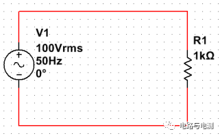
As shown in the figure below, this section explains how to build this circuit on the Multisim working platform.
1) Select components from the component library and place them on the working platform.
Double-click the Multisim icon to run Multisim, click on “Place” → “Component” in the upper left corner. As shown in Figure 1, the “Select a Component” dialog box will appear. In the first field on the left column, select “Master Database”; in the second field, select “Sources” from the dropdown menu; in the third field, click on “POWER_SOURCES”. Then, in the second column, click on “AC_POWER” and click the “OK” button in the upper right corner. The mouse cursor will change to the shape of the selected component. Now, click the left mouse button at an appropriate position on the working platform to place an AC voltage source. The operation sequence is shown in Figure 2.
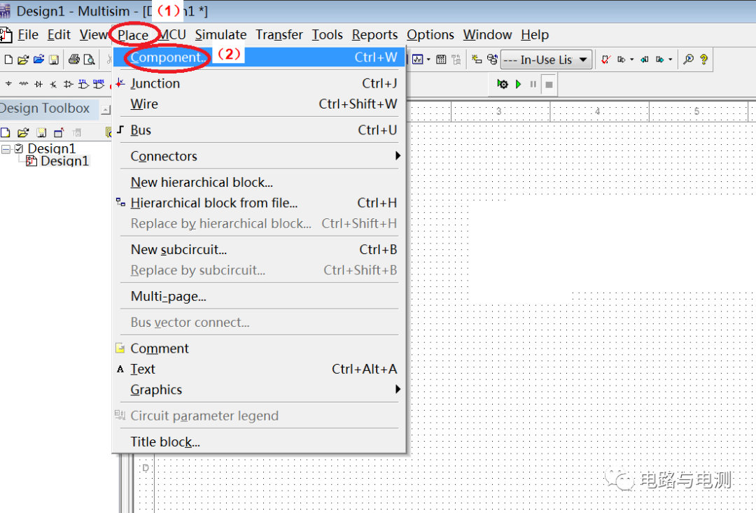
Figure 1: Opening the “Select a Component” dialog box
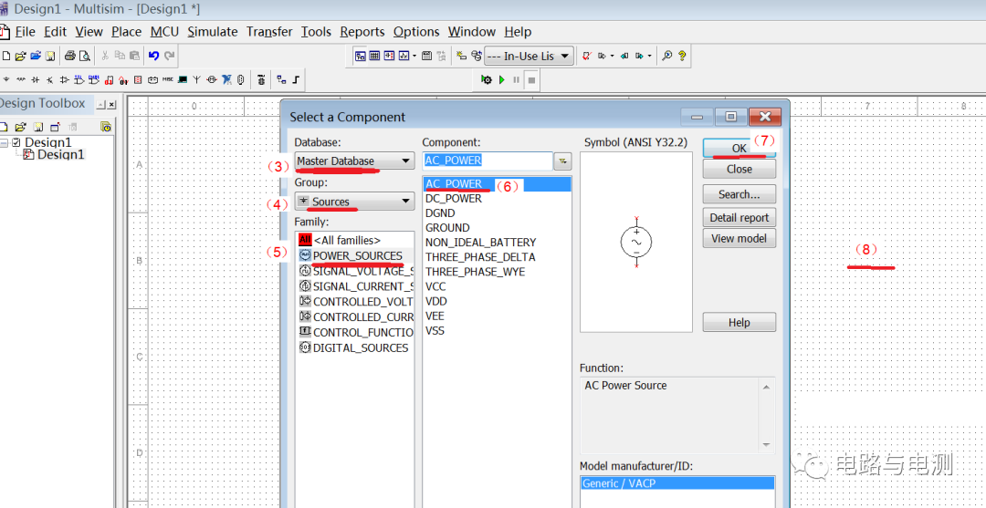
Figure 2: Steps to place an AC power source on the working platform
In the second field of the “Select a Component” dialog box, select “Basic” from the dropdown menu; in the third field, click on “RESISTOR”. In the second column, select “1K” and then click the “OK” button in the upper right corner. After that, click the left mouse button on the working platform to place a resistor.
Close the “Select a Component” dialog box by clicking the “×” in the upper right corner.
At this point, an AC voltage source and a resistor have been placed on the working platform, as shown in Figure 3. You can hold down the “shift” key while scrolling the mouse wheel to zoom in or out of the page. You can also click on a component (a blue dashed box will appear around it) and move it to an appropriate position. Additionally, you can right-click on the resistor component and select “Rotate 90° clockwise” to rotate the resistor by 90°.
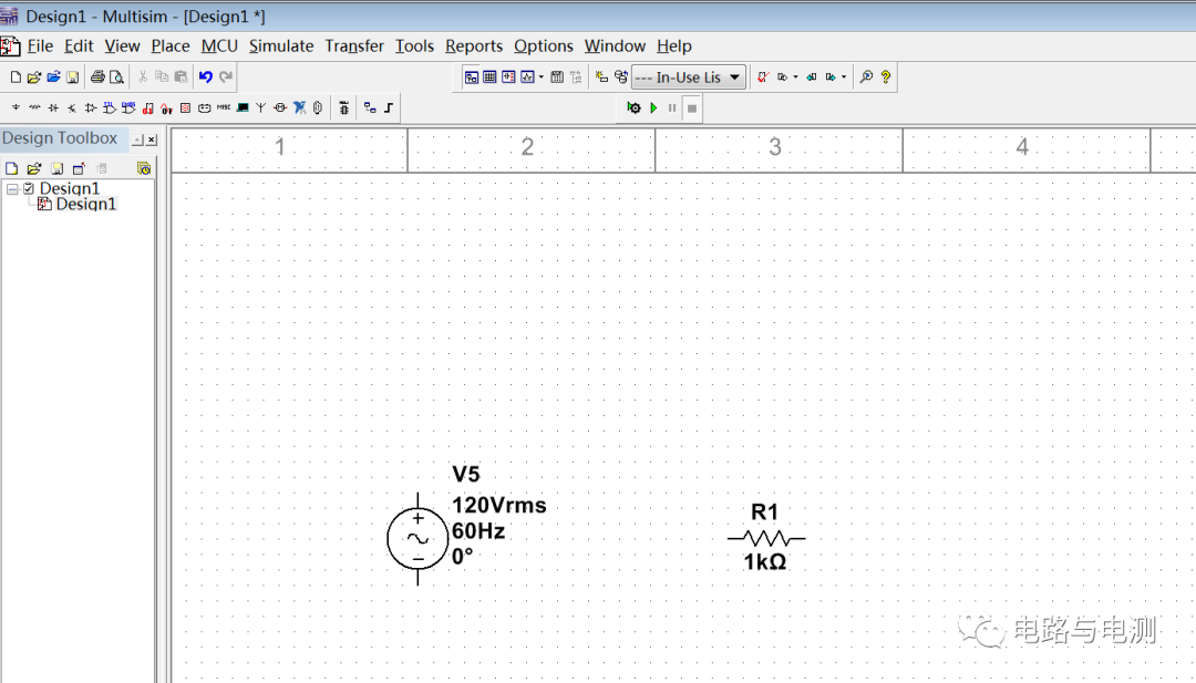
Figure 3: Placing components on the working platform
Double-click the power source component to change its parameters and label (Label), for example, change the effective value of the power source to 100V, the frequency to 50Hz, and the label of the power source to V1 or Vs. Similarly, you can double-click the resistor to change its resistance value and label.
(2) Connect the circuit components on the working platform to establish the circuit model.
On the working platform, when the mouse approaches the component terminal, it will change to a “+” sign. At this point, click the left mouse button, then move the mouse to the terminal of the other component you want to connect to and click the left mouse button again. You will see a wire connecting the two terminals. Follow this operation to connect the power source and the resistor in series, as shown in Figure 4. If you make a mistake during this process, you can click on the drawn wire and press the “Del” key on the keyboard to delete it.
-
Save the file
Click on “File” → “Save” in the upper left corner, choose an appropriate path, name the file “Series Circuit 1”, and click “Save”.
-
Run the program to simulate the circuit.
As indicated by the red arrow in Figure 4, click the green run button, and an error message will appear: The circuit is not grounded. After closing this dialog box,
repeat the first step: click on “Place” → “Component” in the upper left corner, and the “Select a Component” dialog box will appear. In the first field on the left column, select “Master Database”; in the second field, select “Sources” from the dropdown menu; in the third field, click on “POWER_SOURCES”. In the second column, select “GROUND” and click the “OK” button in the upper right corner, as shown in Figure 5, to add a ground to the circuit on the working platform.
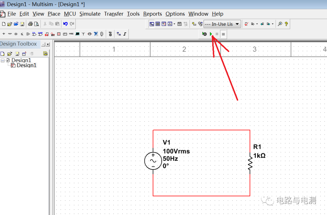
Figure 4: Establishing the circuit model
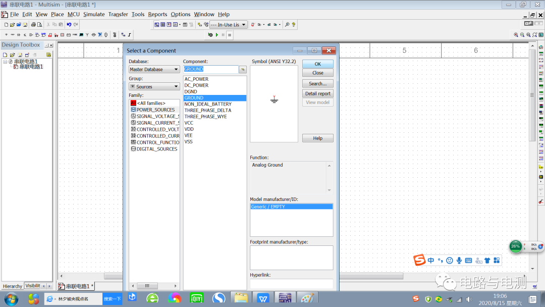
Figure 5: The circuit needs to be grounded
The connected circuit is shown in Figure 6. Click the “Run” button, and there will be no error message.
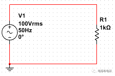
Figure 6: Grounded series circuit
Summary:
The steps to establish a circuit model for simulation using Multisim are as follows:
-
Place the required components from the component library on the working platform;
-
Double-clicking a component allows you to change its symbol and parameters. You can move a component to an appropriate position by clicking on it and holding the left mouse button. You can rotate the component by right-clicking on it and selecting the rotation option; you can delete a component by selecting it and pressing the “Del” key;
-
After connecting the components with wires, the circuit needs to be grounded;
-
Click the “Run” button to simulate the circuit. To end the run, you need to click the “Pause” button or the “End” button next to the “Run” button. Otherwise, clicking the mouse on the working platform will have no effect.
What is the result of the run? You need to use the built-in virtual instruments to test it. An introduction to the virtual instruments will be provided in subsequent content.