Contents
- Introduction to JTAG Boundary Scan BSDL Files
- Contents
- Introduction
- Boundary-Scan Register
- Boundary Scan
- BSDL File Analysis
- Applications of BSDL Files
- Reference
Introduction
BSDL stands for Boundary Scan Description Language, which is a subset of VHDL. It conforms to the syntax standards of VHDL and is used to describe the implementation of JTAG in specified devices. Any device that complies with the JTAG standard must have a corresponding BSDL file.
The BSDL file mainly includes the following information:
- The maximum TCK frequency supported by the current chip
- Definitions of pin names and numbers
- Definitions of power, clock, configuration, IO pins, etc. Each pin’s type, such as VCC, GND, CLK, along with the pin names and numbers
- All available command registers
- All available data registers, including possible preset values, such as the device’s IDCODE
Currently, there are two standards for BSDL: IEEE 1149.1 and IEEE 1149.6. IEEE 1149.6 enriches the content based on the IEEE 1149.1 standard and is compatible with it.
BSDL Resources
- Access to BSDL files from all manufacturers: https://www.bsdl.info/
- Access to Xilinx Zynq BSDL files: C:\Xilinx\Vitis\2020.2\data\parts\xilinx\zynq\public\bsdl
Boundary-Scan Register
Registers under the TAP controller are divided into two main categories: instruction registers and data registers.
The Bypass register, Device Identification register, and Boundary-scan register (boundary scan chain) all belong to the data registers. Among these, the boundary scan register (boundary scan chain) is the most important and frequently used during debugging.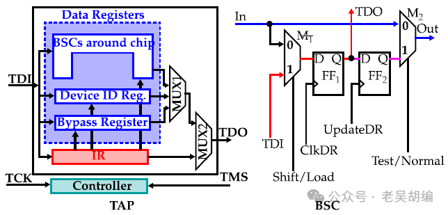
INTEST Command and Boundary-Scan Register:The Boundary-Scan register is the boundary scan chain, and generally, a chip contains multiple boundary scan chains. Through the boundary scan chain, inter-component connectivity testing can be performed. More importantly, it allows observation and control of the input and output of the tested device to achieve testing of the device’s internal logic. The INTEST command is a very important command defined in the IEEE 1149.1 standard: in conjunction with the boundary scan chain, this command allows for internal testing of the system logic of devices on the development board.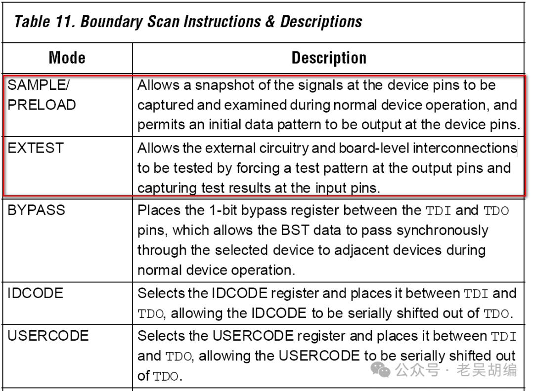
Boundary Scan
When the TAP controller enters the “boundary-scan” state, it means that the IR register has stored the SAMPLE command, EXTEST command, etc. At this point, the corresponding DR register is the boundary scan register, which connects each I/O unit together and can control each pin.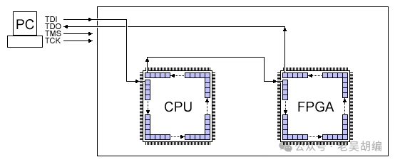
Boundary scan can also be performed during the normal operation of the chip, for example, performing boundary scan on a normally running FPGA can display the state of each pin.
We attempt to read the pin values, and the corresponding IR register command isSAMPLE.
BSDL File Analysis
From the file xc7z020_clg400.bsd, we can determine:
- The length of the IR register is 6 bits;
- The instruction list of the IR instruction register, for example, SAMPLE is 000001
- The length of the boundary scan chain is 1077 bits
The boundary scan register has 1077 bits, but this does not mean there are 1077 pins.
Each pin has an IO pad (chip pin processing module), and the IO pad uses 1 to 3 bits of registers (depending on whether the pin is input, tri-state output, or input/output). Of course, some registers contained in the IO pad may not be included in the boundary scan chain.xc7z020_clg400.bsd:
-- Instruction Register Description
attribute INSTRUCTION_LENGTH of XC7Z020_CLG400 : entity is 6;
attribute INSTRUCTION_OPCODE of XC7Z020_CLG400 : entity is
        "IDCODE         (001001)," & -- DEVICE_ID
        "BYPASS         (111111)," & -- BYPASS
        "EXTEST         (100110)," & -- BOUNDARY
        "SAMPLE         (000001)," & -- BOUNDARY
        "PRELOAD        (000001)," & -- Same as SAMPLE
        "USERCODE       (001000)," & -- DEVICE_ID
        "HIGHZ          (001010)," & -- BYPASS
        "EXTEST_PULSE   (111100)," & -- BOUNDARY
        "EXTEST_TRAIN   (111101)," & -- BOUNDARY
        "ISC_ENABLE     (010000)," & -- ISC_CONFIG
        "ISC_PROGRAM    (010001)," & -- ISC_PDATA
-- Boundary-Scan Register Description
attribute BOUNDARY_LENGTH of XC7Z020_CLG400 : entity is 1077;
attribute BOUNDARY_REGISTER of XC7Z020_CLG400 : entity is
-- cellnum (type, port, function, safe[, ccell, disval, disrslt])
        "   0 (BC_2, *, internal, 1)," &
        "   1 (BC_2, *, internal, 0)," & --  RSVDGND_0
        "   2 (BC_2, *, internal, X)," & --  RSVDGND_0
        "   3 (BC_2, RSVDVCC3_N6, input, X)," &
        "   4 (BC_2, RSVDVCC2_R6, input, X)," &
        "   5 (BC_2, RSVDVCC1_T6, input, X)," &
        "   6 (BC_2, CFGBVS_M6, input, X)," &
        "   7 (BC_2, *, internal, 1)," & --  PROGRAM_B
        "......," &
        "1063 (BC_2, *, internal, 1)," & -- PS_SRST_B
        "1064 (BC_2, *, internal, X)," &
        "1065 (BC_2, *, internal, X)," &
        "1066 (BC_2, *, internal, X)," &
        "1067 (BC_2, *, internal, X)," &
        "1068 (BC_2, *, internal, X)," &
        "1069 (BC_2, *, internal, X)," &
        "1070 (BC_2, *, internal, X)," &
        "1071 (BC_2, *, internal, X)," &
        "1072 (BC_2, *, internal, X)," &
        "1073 (BC_2, *, internal, X)," &
        "1074 (BC_2, *, internal, X)," &
        "1075 (BC_2, *, internal, X)," &
        "1076 (BC_2, *, internal, X)";
Applications of BSDL Files
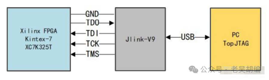
BSDL files can be used in various boundary scan software, such as XJTAG, TopJTAG, etc. By loading the corresponding BSDL file, it is possible to read and control all external pins of the chip.
-
Tool TopJtag:
- TopJTAG Probe: Boundary scan testing software that can read and control IO, display waveforms, count pulses, etc.
- TopJTAG Flash Programmer: Can program and read external CFI Flash of the chip.
- IO testing steps using the 100t development board:1. Create a new project to establish JTAG connection; some Digilent JTAG can be recognized directly.
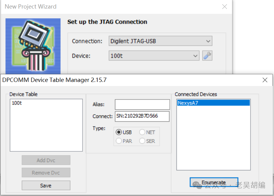
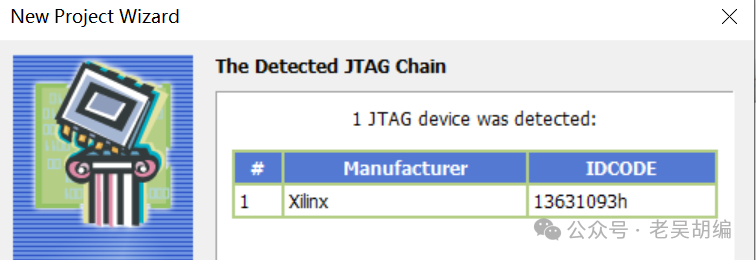 2. Select the BSDL file C:\Xilinx\SDK\2018.3\data\parts\xilinx\artix7\public\bsdl\xc7a100t_csg324.bsd, initially in SAMPLE state, which can be adjusted through instruction.3. IO can add waveform viewing.In the JTAG chain view, different colors represent different IO states. Pin values are color-coded. Black means 0, red — 1, brown — high-Z, and blue — linkage pin.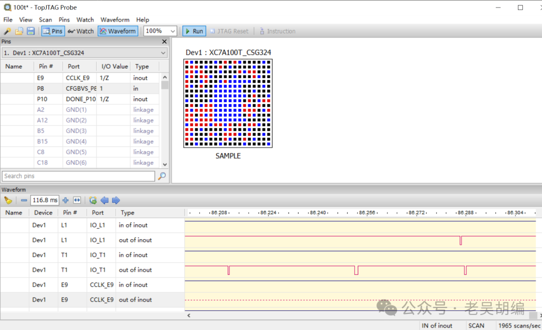
Reference
IEEE Standard 1149.1 – Test Access Port and Boundary-Scan Architecture