Skip to content
The Development of Process Control Instruments and Control Systems Has Gone Through Four Stages:1. In the 1950s, pneumatic unit combined instruments were the main focus. 2. In the 1960s, the emergence of electronic components like transistors allowed for the development and application of electric unit combined instruments (DDZⅡ). 3. In the 1970s, safety spark explosion-proof unit combined instruments (DDZⅢ), assembled instruments, and circuit detection instruments were developed using linear integrated circuits and small-scale digital circuits. 4. In the 1980s, microprocessors and integrated circuits were adopted, applying microcomputer technology to instrument control systems, resulting in centralized management with decentralized control systems and digital unit combined instruments.
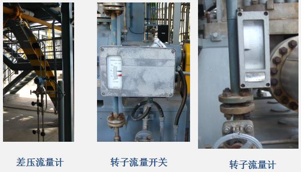
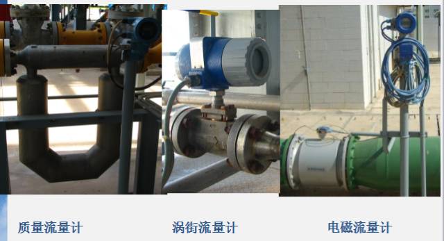
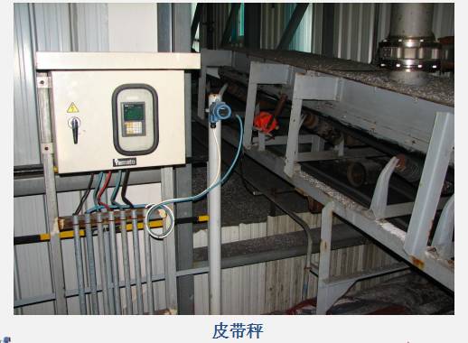
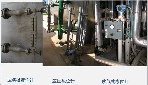
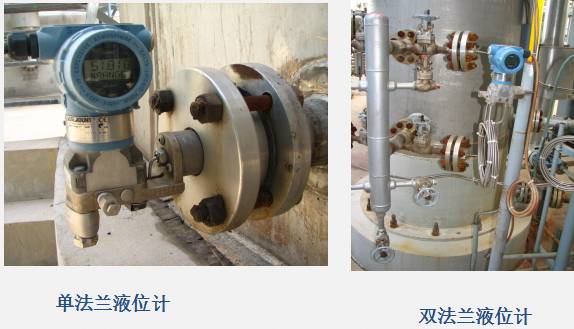
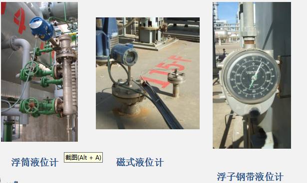
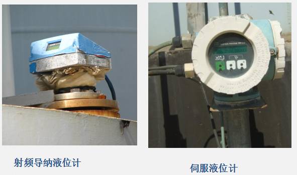
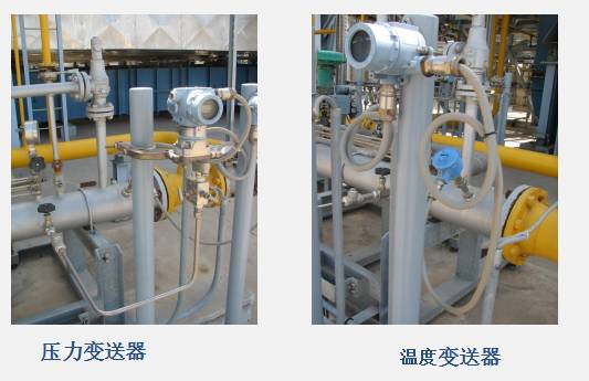
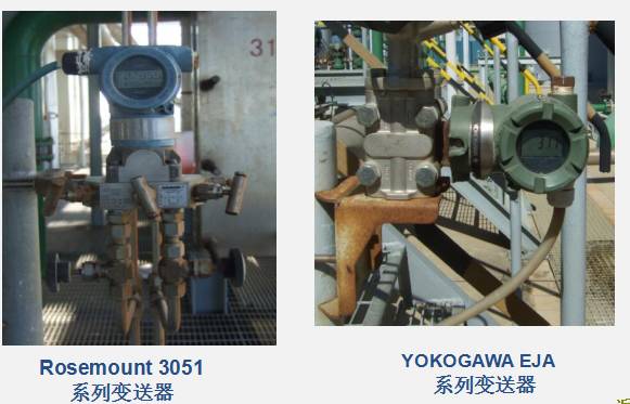
1. Detection Instruments1. Temperature transmitters (thermocouples, thermal resistors, expansion type, pressure type, radiation type, etc.) 2. Pressure/differential pressure transmitters (liquid column type, elastic type, electrical type, piston type, etc.) 3. Level transmitters (direct reading type, differential pressure type, float type, nuclear radiation, ultrasonic type, etc.) 4. Flow transmitters (velocity type, volumetric type, mass type, etc.)
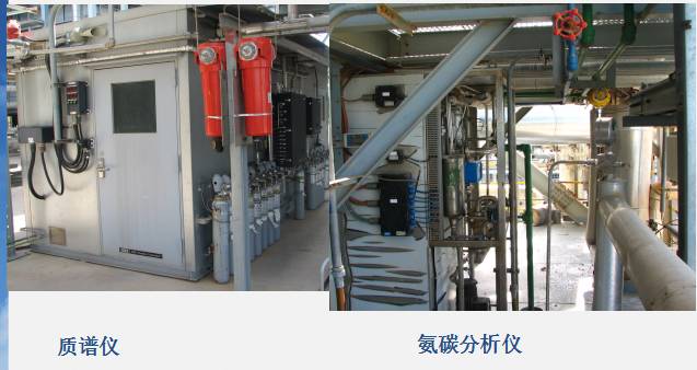
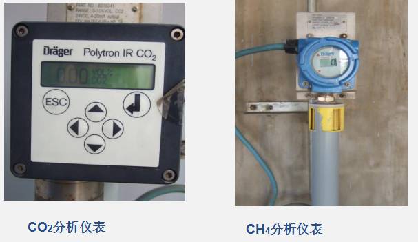
2. Analyzers Analyzers are instruments used to measure the composition, content, and certain physical properties of substances (including mixtures and compounds). The analysis instruments in the fertilizer department include: ammonia nitrogen concentration analyzer, chromatograph, moisture analyzer, oxygen content analyzer, density meter, pH meter, SiO2 analyzer, infrared analyzer, etc.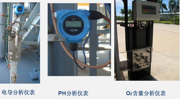
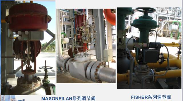
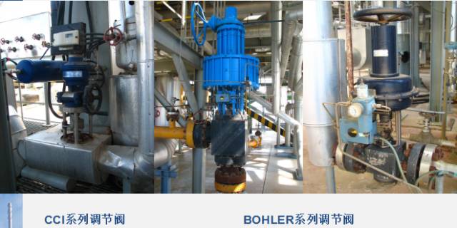
Actuators are an essential part of automatic control systems. Their role in the system is to receive output signals from the regulator, change the regulated parameters, and keep the controlled parameters within the required range, thus achieving automation in the production process. Actuators replace manual operations and are metaphorically referred to as the “hands and feet” that achieve automation in the production process.
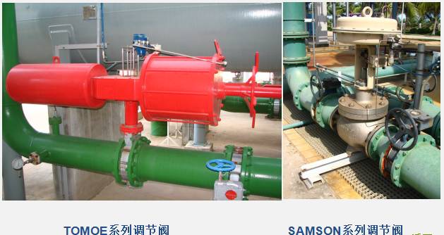
Actuators can be classified based on the energy used: pneumatic actuators, electric actuators, and hydraulic actuators. Among these, pneumatic actuators are the most commonly used in industrial control.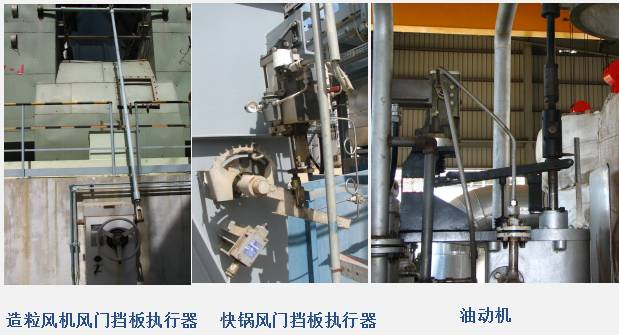 Control Valves (also known as Control Valve) consist of two parts: Control Valve = Actuator + Valve Body Components
The actuator is the driving device of the control valve. It generates corresponding thrust based on the magnitude of the signal pressure, causing the push rod to produce corresponding displacement, thereby driving the valve core of the control valve to act. The valve body components are the regulating parts of the control valve that come into direct contact with the medium, changing the regulating flow area based on the valve core’s action to achieve regulation.
Control Valves (also known as Control Valve) consist of two parts: Control Valve = Actuator + Valve Body Components
The actuator is the driving device of the control valve. It generates corresponding thrust based on the magnitude of the signal pressure, causing the push rod to produce corresponding displacement, thereby driving the valve core of the control valve to act. The valve body components are the regulating parts of the control valve that come into direct contact with the medium, changing the regulating flow area based on the valve core’s action to achieve regulation.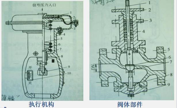
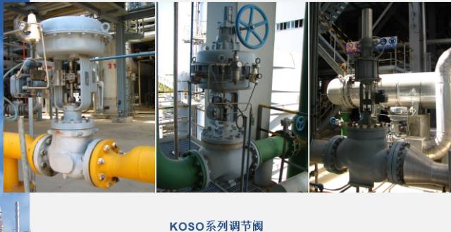
1. Control Valve Classification
Control valves are classified into Pneumatically Open Valves and Pneumatically Closed Valves.
The opening and closing forms of control valves are divided into pneumatically open and pneumatically closed. Pneumatically open means that when the control pressure input to the actuator increases, the valve moves in the direction of opening, increasing the flow of the medium through the valve; pneumatically closed is the opposite, where the valve moves in the direction of closing when the control pressure increases.
The determination of the opening and closing form of control valves is primarily considered from the perspective of safe production. For example, in boilers, the control valves for fuel gas are usually pneumatically open. When there is a fault that interrupts the control pressure signal, the actuator’s pressure is zero, and the valve can remain closed. This cuts off the fuel gas to prevent excessive internal temperatures and potential hazards.
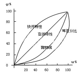
2. Control Valve Characteristics
Flow Characteristics of Control Valves: The ideal flow characteristic of a control valve refers to the relationship between the relative flow of the medium passing through the valve and the relative opening of the valve (relative displacement) when the pressure difference before and after the control valve remains constant.
There are four types of ideal flow characteristics for control valves: 1. Linear characteristics 2. Equal percentage characteristics 3. Quick opening characteristics 4. Parabolic characteristics
DCS Distributed Control System 2.PLC Programmable Logic Controller 3.SIS Safety Instrumented System 4.ITCC
Integrated Turbine & Compressor Control
DCS:DCS—Distributed Control System, as defined by ISO: To meet the requirements of large-scale industrial production and increasingly complex process control, it is conceived according to the principles of decentralized control and centralized management, combining microprocessors, communication technology, human-machine interface technology, and I/O interface technology for data collection, process control, and production management.
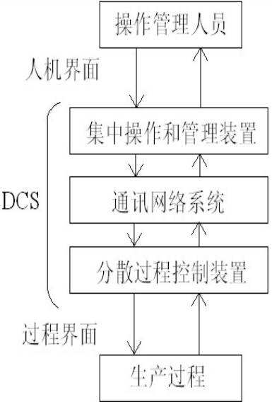
It is a centralized and decentralized integrated control system based on microprocessors. Centralized refers to centralized management, operation, and display, while decentralized refers to decentralized control and risk. It is mainly divided into three major parts: controllers with I/O components, communication networks, and human-machine interfaces (HMI).
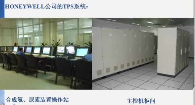
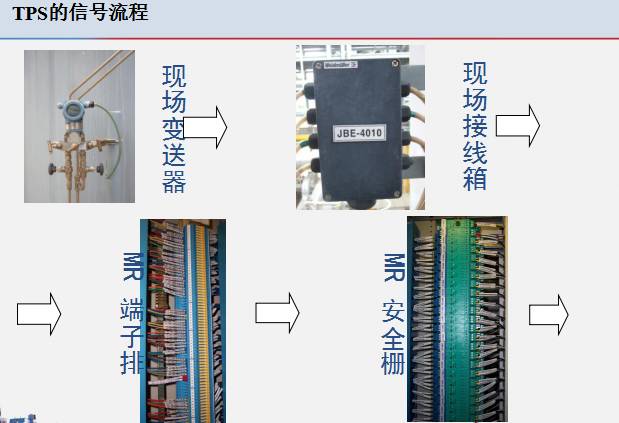
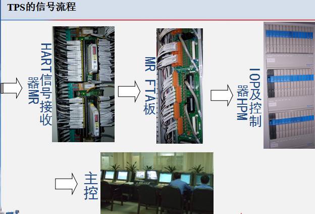
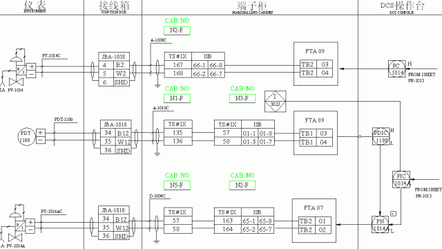
The TPS system is an open factory automation system developed by Honeywell. It mainly consists of a high-performance process manager (HPM), network interface module (NIM), historical module (HM), global user operation station (GUS), engineer station, and local control network (LCN), universal control network (UCN), etc.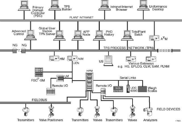 1. High Performance Process Manager HPM 2. Network Interface Module NIM 3. History Module HM 4. Global User Station GUS 5. Enhanced Programming Logic Controller Gateway EPLCG 6. Safety Manager SM
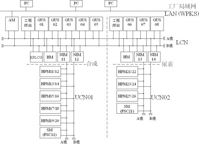
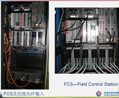
The CENTUM CS system is a product of Yokogawa Electric Corporation, and the fertilizer department uses its CS1000 system. The CS system mainly consists of engineer station (EWS), information instruction station (ICS), dual redundant field control station (AFM20D), communication gateway unit (ACG), and dual redundant communication network (V-NET).
Monitoring Point Count: 8000
Maximum Number of Stations: 24 (including field control stations and human-machine interface stations)
Human-Machine Interface Stations: 8
Field Control Stations: 16
Communication Network (VL net): 185m coaxial cable (or 20km fiber optic cable), data transmission rate of 10Mbps.
CS1000 mainly consists of the following five basic components.
HIS (Human-Machine Interface Station) FCS (Field Control Station)
V-net (Control Bus) BCV (Bus Converter)
CGW (Communication Gateway)
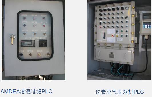
PLC— Programmable Logic Controller
The Programmable Logic Controller is a logic and sequential control device with a microprocessor as its core component. It is a digital electronic device that uses programmable memory to store instructions and implement functions such as logic operations, sequential operations, counting, timing, and arithmetic operations, used for controlling various machinery and production processes.
The fertilizer department mainly uses PLCs produced by Mitsubishi Electric, Rockwell Automation (Allen-Bradley), Schneider Electric (Modicon), etc.
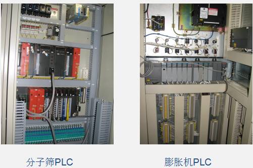
The molecular sieve uses Mitsubishi Electric’s Q series PLC, while some small PLCs on-site like 104L, 115L, instrument air dryers, and finished product packaging scales use the F series PLC.
The expander uses Rockwell Automation (Allen-Bradley) PLC.
The finished product control system uses Schneider Electric (Modicon) PLC.
SIS is the abbreviation for Safety Instrumented System. Currently, there are two other different names internationally: ESD, which stands for Emergency Shutdown Device, and IPS, which stands for Instrumented Protective System. These terms all refer to using instrument systems for protection, and are referred to as SIS in the International Electrotechnical Commission (IEC) and TUV certification bodies.
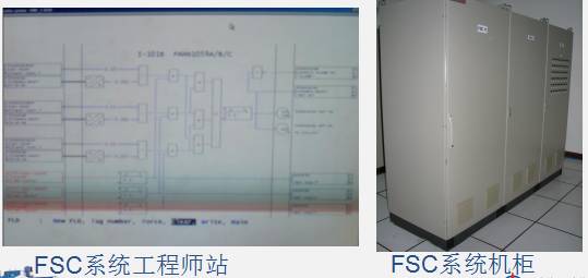
The fertilizer department mainly uses Honeywell’s FSC and HIMA’s H41q (used for BMS) two sets of SIS.
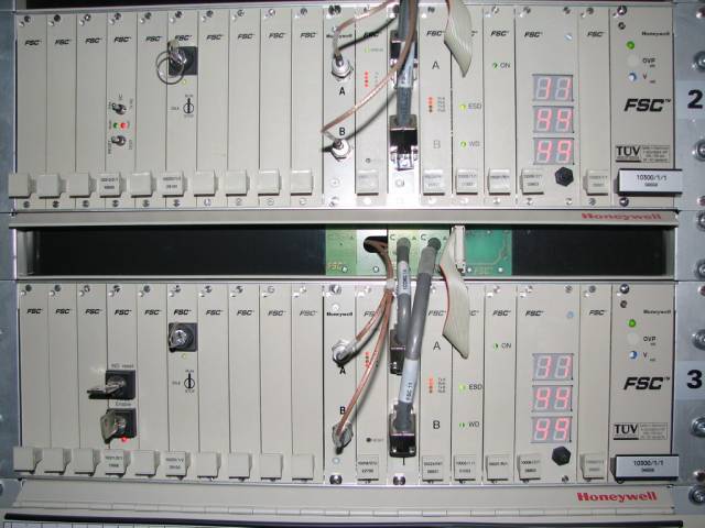
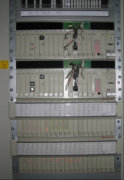
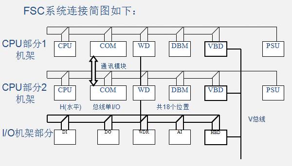
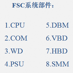
The main SIS used in the fertilizer department is FSC-Fail Safety Control, which is a safety management system produced by HONEYWELL that can quickly isolate faulty hardware from normal components and protect the system.
The medium-pressure boiler 2201U uses the boiler management system (BMS), which is also a type of SIS. It utilizes HIMA’s fault-tolerant control system H41q, which adopts a quadruple redundancy fault tolerance structure (QMR technology).
The main device of the fertilizer department has a total of 6 compressor units: raw gas compressor unit (102J/JT), synthesis gas compressor unit (103J/JT), ammonia refrigeration compressor unit (102J/JT), ammonia booster (105J1/JAM), carbon dioxide compressor unit (302J/JT), and process air compressor unit (101J/JGT). Among them, the process air compressor unit (101J/JGT) is driven by a gas turbine, and the unit control uses GE’s Speedtronic Mark VI control system. The other units all use the MicroNet TMR control system produced by Woodward, with a total of 4 sets (105J1 is motor-driven and shares a set with 102J/JT).
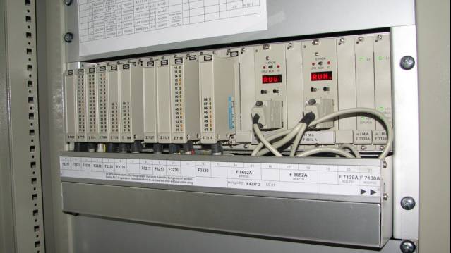
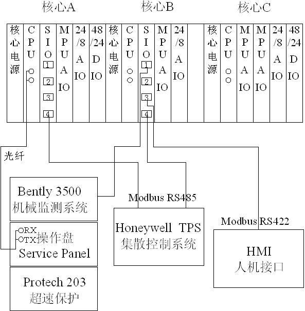
The MicroNet control system is a system based on a 32-bit microprocessor. The cards are inserted into a rack, which can be expanded to 6-slot, 12-slot, and 18-slot configurations. The MicroNet TMR control system consists of an 18-slot rack (with 3 core parts, 6 slots/core part) and a redundant power supply rack. The MicroNet platform is developed based on the VME (VERSA Module Eurocard) backplane, with the CPU card located in the first valid slot of the VME rack. All I/O cards are inserted into the remaining VME rack slots, and extension racks can be used to increase I/O cards. The system configuration diagram is as follows:
The ammonia synthesis production unit uses the SPEEDTRONIC Mark VI TMR heavy-duty industrial gas turbine control system, which controls a gas turbine produced by GE Nuovo Pignone (MS5002C), 2MCL 1007, and 2BCL 457 centrifugal compressors. The gas turbine cycle is a simple cycle, and most of the exhaust from the gas turbine is used as combustion air for a section of the conversion furnace, while a small portion is vented or directly enters the convection section of a section of the furnace.
The SPEEDTRONIC™ Mark VI turbine control system is a next-generation comprehensive turbine control system designed and manufactured by General Electric (GE). The Mark VI can implement complete integrated control, protection, and monitoring of prime movers (steam turbines or gas turbines), generators, compressors, and more.


