
1. Functions of Industrial Robot Control Systems
The robot control system is a crucial component of the robot, used to control the operation of the machine to complete specific tasks. Its basic functions are as follows:
1. Memory Function: Stores job sequences, motion paths, motion modes, motion speeds, and information related to production processes.
2. Teaching Function: Offline programming, online teaching, and indirect teaching. Online teaching includes teaching boxes and guided teaching.
3. Peripheral Device Connection Function: Input and output interfaces, communication interfaces, network interfaces, synchronization interfaces.
4. Coordinate Setting Function: Includes joint, absolute, tool, and user-defined coordinate systems.
5. Human-Machine Interface: Teaching box, operation panel, display screen.
6. Sensor Interface: Position detection, vision, touch, force, etc.
7. Position Servo Function: Multi-axis linkage, motion control, speed and acceleration control, dynamic compensation, etc.
8. Fault Diagnosis and Safety Protection Function: Monitoring system status during operation, safety protection under fault conditions, and fault self-diagnosis.
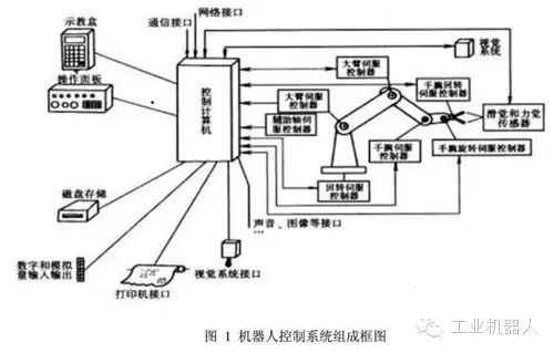
2. Composition of Industrial Robot Control Systems
1. Control Computer: The scheduling and command center of the control system, generally a microcomputer or microprocessor (32-bit, 64-bit), such as the Pentium series CPU and other types of CPUs.
2. Teaching Box: Used to teach the robot’s working trajectory and parameter settings, as well as all human-machine interaction operations. It has its own independent CPU and storage unit, communicating with the main computer via serial communication.
3. Operation Panel: Composed of various operation buttons and status indicator lights, only completes basic functional operations.
4. Hard Disk and Floppy Disk Storage: Peripheral storage for storing robot working programs.
5. Digital and Analog Input/Output: Input or output of various status and control commands.
6. Printer Interface: Records various information that needs to be output.
7. Sensor Interface: Used for automatic detection of information, achieving robot compliance control, generally includes force, touch, and vision sensors.
8. Axis Controller: Controls the position, speed, and acceleration of each joint of the robot.
9. Auxiliary Device Control: Controls auxiliary devices that cooperate with the robot, such as gripper positioners.
10. Communication Interface: Facilitates information exchange between the robot and other devices, generally includes serial and parallel interfaces.
11. Network Interface:
1) Ethernet Interface: Allows direct PC communication with multiple or single robots via Ethernet, with a data transmission rate of up to 10Mbit/s. It supports TCP/IP communication protocol and can program applications on PC using Windows library functions, loading data and programs into various robot controllers via the Ethernet interface.
2) Fieldbus Interface: Supports multiple popular fieldbus specifications, such as DeviceNet, AB Remote I/O, Interbus-S, Profibus-DP, M-NET, etc.
3. Classification of Industrial Robot Control Systems
1. Program Control System: Applies a certain control pattern to each degree of freedom, enabling the robot to achieve the desired spatial trajectory.
2. Adaptive Control System: Adjusts control quality based on changes in external conditions to maintain required quality or improve control quality over time. This process is based on observing the state of the operation machine and servo error, and adjusting the parameters of the nonlinear model until the error disappears. The structure and parameters of this system can change automatically over time and conditions.
3. Artificial Intelligence System: Does not have a pre-programmed motion sequence but determines control actions in real-time based on surrounding state information obtained during movement.
4. Point Positioning: Requires the robot to accurately control the pose of the end effector, regardless of the path.
5. Trajectory Control: Requires the robot to move along the taught trajectory and speed.
6. Control Bus: An international standard bus control system. Uses international standard buses as the control bus for the control system, such as VME, MULTI-bus, STD-bus, PC-bus.
7. Custom Bus Control System: Uses a bus defined by the manufacturer as the control bus for the control system.
8. Programming Method: Physically set programming system. The operator sets fixed limit switches to implement the start and stop operations, only suitable for simple pick-and-place tasks.
9. Online Programming: Completes the memory process of operation information through human teaching, including direct teaching, simulated teaching, and teaching box teaching.
10. Offline Programming: Does not directly teach the robot for actual operations but teaches away from the actual work environment.
4. Structure of Robot Control Systems
Robot control systems can be classified into three types based on their control methods.
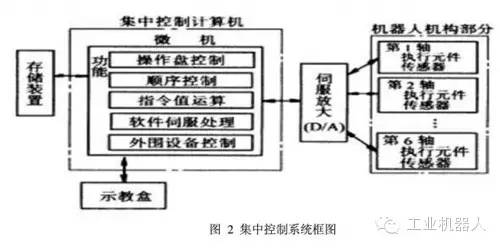
1) Centralized Control System: Uses a single computer to implement all control functions, with a simple structure and low cost, but poor real-time performance and difficult to expand. This structure was commonly used in early robots, as shown in the block diagram in Figure 2.
In PC-based centralized control systems, the open characteristics of PC resources are fully utilized, allowing for good openness: various control cards and sensor devices can be integrated into the control system via standard PCI slots or standard serial and parallel ports. The advantages of centralized control systems include lower hardware costs, ease of information collection and analysis, ease of achieving optimal system control, and good integrity and coordination. However, its disadvantages are also evident: the system control lacks flexibility, control risks are easily centralized, and once a fault occurs, the impact is wide and severe. Due to the high real-time requirements of industrial robots, performing large amounts of data calculations can reduce system real-time performance, and the system’s response capability to multiple tasks may conflict with its real-time performance. Additionally, complex wiring can reduce system reliability.
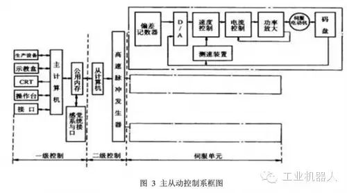
2) Master-Slave Control System: Uses a master and slave processor to implement all control functions. The master CPU manages coordinate transformations, trajectory generation, and system self-diagnosis, while the slave CPU controls all joint movements. This structure, shown in Figure 3, has better real-time performance and is suitable for high-precision, high-speed control, but it has poor system expandability and maintenance difficulties.
3) Distributed Control System: Divides the control system into several modules based on the nature and method of the system, with each module having different control tasks and strategies. The relationships between modes can be hierarchical or equal. This method has good real-time performance, is easy to achieve high-speed and high-precision control, and is easy to expand, making it a popular approach today, as shown in the control block diagram in Figure 4.
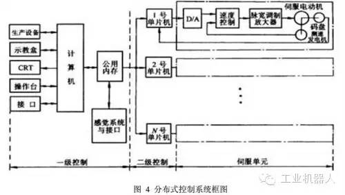
The main idea is “distributed control, centralized management,” meaning the system can comprehensively coordinate and allocate its overall goals and tasks, and complete control tasks through the coordinated work of subsystems. The entire system is decentralized in terms of functionality, logic, and physical aspects, so DCS systems are also known as decentralized control systems. In this structure, subsystems consist of controllers and different controlled objects or devices, and each subsystem communicates with others via networks. The distributed control structure provides an open, real-time, and precise robot control system. Distributed systems often employ a two-level control method.
The two-level distributed control system typically consists of an upper computer, a lower computer, and a network. The upper computer can perform different trajectory planning and control algorithms, while the lower computer conducts research and implementation of interpolation subdivision and control optimization. The upper and lower computers coordinate their work through a communication bus, which can take the form of RS-232, RS-485, IEEE-488, or USB buses.
Currently, the development of Ethernet and fieldbus technology provides robots with faster, more stable, and effective communication services. Especially fieldbus, which is applied in production sites to achieve bidirectional multi-node digital communication between microcomputer measurement and control devices, forming a new integrated network distributed control system—Fieldbus Control System (FCS). In factory production networks, devices connected via fieldbus are collectively referred to as “field devices/instruments.” From a systems theory perspective, industrial robots, as one of the production devices in factories, can also be categorized as field devices. The introduction of fieldbus technology in robot systems facilitates the integration of robots in industrial production environments.
The advantages of distributed control systems include good system flexibility, reduced risks in the control system, and the use of multi-processor decentralized control, which is beneficial for parallel execution of system functions, improving processing efficiency and shortening response time.
For industrial robots with multiple degrees of freedom, centralized control handles the coupling relationship between control axes well and can easily perform compensation. However, when the number of axes increases to make the control algorithm complex, its performance will deteriorate. Additionally, when the number of axes or the complexity of the control algorithm increases, it may lead to system redesign. In contrast, in a distributed structure, each motion axis is handled by a controller, which means there is less coupling between axes and higher system reconfigurability.
Source: Compiled from online materials on industrial robots
Business Cooperation: 010—88379790 ext. 802, 822
Disclaimer: This article is a network reprint, and the copyright belongs to the original author. However, due to numerous reprints, it is impossible to confirm the original author, so only the source of the reprint is indicated. If there are copyright issues with the videos, images, or text used in this article, please inform us immediately, and we will confirm the copyright based on the materials you provide and pay remuneration according to national standards or delete the content immediately! The content of this article represents the views of the original author and does not reflect the views of this public account or its responsibility for its authenticity.

Reply 4: Join the Industrial Robot Technology Exchange Group 4 (focusing on industrial robot applications, automated production lines, etc.)
Reply 5: Join the Industrial Robot Technology Exchange Group 5 (focusing on the composition of industrial robots, including the body, drive system, control system, etc.)
Reply 6: Join Group 6 (focusing on PLC technology, programming technology, etc.)