——————————————————————————————————————————
Copyright Statement:
Author: Wang Weiwei. Mainly engaged in ISP/GPU/video/automotive chips/AI chips/SoC architecture design
Zhihu Column: Advanced Path of Chip Design
WeChat Official Account: Advanced Path of Chip Design (x_chip)
Can be forwarded without authorization, but this statement must be retained, otherwise legal action will be taken!
——————————————————————————————————————————
Currently, we are in a data-driven intelligent era. Whether it is the brain of autonomous driving cars, AI accelerators driving large language models (LLM), or mobile devices providing immersive experiences, the core is a SoC chip with increasingly powerful functions. These SoCs share a common feature of high heterogeneity: general-purpose CPU clusters, high-performance GPUs, dedicated neural network processing units (NPU), image signal processors (ISP), and digital signal processors (DSP) all share an on-chip network (NoC) and a unified memory subsystem.
This architecture provides powerful computing power while also bringing unprecedented resource competition issues. For example, a data access request from an autonomous driving task executing critical path decisions may be delayed by an infotainment system rendering high-definition maps; an AI inference task may suffer from insufficient NPU data supply due to a sudden high bandwidth demand from the CPU, resulting in “computing power idling.” If these issues are not effectively managed, it will lead to a significant decline in system performance, uncertain response times for critical tasks, and even catastrophic consequences in safety-critical areas such as automotive. Therefore, the establishment of a QoS system aims to provide predictable performance guarantees (such as latency and bandwidth) for different tasks through refined management and scheduling of on-chip resources, thereby addressing resource conflicts in heterogeneous multi-core environments, which is one of the core issues in current SoC design.
1. Definition and Challenges of QoS Systems
Before discussing QoS (Quality of Service), let’s define what QoS is. This concept originates from network communication. Although it translates to “service quality,” its meaning in SoC is far from a literal translation. In this article, the QoS system refers to a set of mechanisms and strategies used to manage and allocate shared on-chip resources (including NoC bandwidth, memory bandwidth, cache space, I/O, etc.), aiming to ensure that transactions initiated by different processing units (Masters) can meet their specific performance requirements.
Building such a system faces many challenges:
-
End-to-end complexity: QoS requirements originate from applications, but their guarantees must span the operating system (OS), drivers, on-chip interconnect networks, and ultimately reach hardware levels such as memory controllers. Any missing link will break the QoS chain.
-
Diversity of requirements due to heterogeneity: CPU cores focus on low latency, GPUs require high throughput, while real-time processing units (such as automotive MCUs) demand deterministic upper bounds on latency. How to meet these vastly different requirements with a unified framework is a huge challenge.
-
Dynamic and adaptive nature: System load is dynamically changing. An efficient QoS system must be able to monitor system status in real-time and dynamically adjust resource allocation strategies to adapt to constantly changing application scenarios.
-
Trade-off between performance and cost: Overly complex QoS hardware will increase chip area and power consumption, while overly simple mechanisms (such as static priority arbitration) cannot effectively cope with complex competition scenarios.
2. Core Principles and Architecture of QoS Systems
A successful QoS system design begins with clear top-level design principles and a layered architecture.
2.1. End-to-End QoS Concept
End-to-end is the primary principle of SoC QoS system design. This means that QoS control must extend from the transaction initiation point (such as CPU cores or GPUs) all the way to the final service point (such as memory controllers or I/O peripherals), covering all shared resource nodes along the path (such as NoC routers and caches). A typical end-to-end QoS path is as follows:
Application Layer -> OS/Middleware -> Drivers -> Hardware Master Interface -> On-chip Network (NoC) -> Hardware Slave Interface -> Memory Controller
In this chain, applications express their performance requirements (e.g., high priority, low latency requirements) to the operating system through APIs. The operating system and middleware are responsible for translating these abstract requirements into specific hardware QoS parameters and configuring them into the underlying hardware modules through drivers. This end-to-end perspective ensures the global consistency of QoS strategies.
2.2. Layered Architecture Model
To effectively manage end-to-end complexity, a layered architecture model is proposed:
-
Application & Service Layer: Located at the top layer, it is the source of QoS requirements. Different applications (such as real-time control, video decoding, AI inference) define different service level objectives (SLO) based on their business characteristics.
-
System Software Layer: The core layer that connects the upper and lower layers. It includes the operating system, hypervisor, and middleware. The main responsibilities of this layer are:
-
QoS Policy Management: Deciding global QoS policies based on the current system scenario (such as gaming mode, autonomous driving mode) and application requirements.
-
Requirement Translation and Mapping: Translating the abstract requirements of upper-layer applications (such as “real-time”) into parameters recognizable by lower-layer hardware (such as priority ID, bandwidth quota, latency targets).
-
Resource Monitoring and Dynamic Adjustment: Monitoring hardware performance counters to perceive system bottlenecks and dynamically adjust QoS configurations.
-
Hardware Abstraction Layer (HAL): Hides the complexity and diversity of underlying hardware, providing a unified QoS configuration interface for upper-layer software.
-
Hardware Implementation Layer: The physical carrier of QoS mechanisms. It includes arbiters in NoC, schedulers in memory controllers, and various performance monitoring units (PMU) and other physical IPs.
2.3. Key QoS Metrics
Within the SoC, QoS measurement mainly revolves around the following core metrics:
-
Latency: The time required for a transaction from initiation to completion and response. Especially “tail latency” (such as 99th percentile latency) is crucial for real-time systems and interactive applications.
-
Bandwidth: The amount of data that can theoretically be transmitted in a unit of time. The QoS system needs to provide “guaranteed bandwidth” for critical paths while efficiently utilizing the remaining “peak bandwidth.”
-
Throughput: The effective amount of data or number of tasks successfully processed or transmitted by the system under actual workloads in a unit of time.
-
Fairness: Ensuring that different requesters receive a reasonable share of resources during resource competition, preventing “starvation” phenomena.
3. Establishing QoS Systems
The goal of establishing a QoS system is:To distinguish and schedule various concurrent data flows in the system based on their characteristics (such as latency sensitivity, bandwidth requirements, real-time requirements) to meet the overall system’s performance, functionality, and power consumption requirements.
Core Methodology: Layering and Collaboration
The mainstream approach in the industry is no longer the independent design of single modules, but rather a layered, collaborative “system view,” as shown in the following diagram:
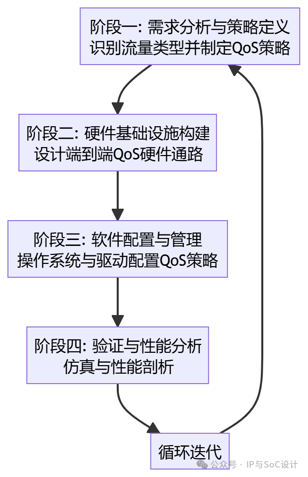
Phase 1: Requirement Analysis and Policy Definition
1. Traffic Identification and Classification:
First, it is necessary to identify all possible master devices (Masters) that may generate data flows in the system: CPU clusters, GPUs, NPUs, DMAs, video codecs, network interfaces, etc.
Label these data flows for classification, usually divided into several major categories:
Latency-sensitive: CPU instruction fetching, cache maintenance, interrupt control, touch feedback, audio playback.Goal: Low latency.
Bandwidth-sensitive: GPU texture rendering, video frame transmission, memory copying (DMA).Goal: High bandwidth.
Real-time guarantee: Display controllers (must send new data before the next frame scan), automotive safety buses.Goal: Deterministic latency and bandwidth, with no jitter.
Best effort: Background network downloads, disk defragmentation.Goal: Process if there are idle resources, with no guarantees.
2. Formulating QoS Policies:
Based on classification, allocate system resources (bus bandwidth, memory bandwidth) according to priority.
For example:
Policy 1: Real-time requests from the CPU (Latency-Sensitive) have the highest priority and can preempt any other requests.
Policy 2: Bandwidth requests from the GPU (Bandwidth-Sensitive) enjoy the highest weight, ensuring 80% of available bandwidth.
Policy 3: The display DMA controller uses fixed time slices (TDMA), ensuring that 60 frames of data per second must be delivered on time.
Phase 2: Building Hardware Infrastructure
This is the physical foundation of the QoS system, requiring the deployment of a series of hardware units across the entire data path.
1. Issuing and Transmitting QoS Identifiers:
Master devices must carry QoS identifier information when initiating requests. In the AMBA AXI/ACE protocol, this is represented by <span>ARQOS</span>/<span>AWQOS</span> signals (4 bits, 16 priority levels).
This QoS label will accompany the entire transaction as it traverses the interconnect network, caches, and ultimately reaches the memory controller.
2. QoS Support in Interconnect Networks:
Key Components: Interconnect IPs with advanced QoS features (such as SNPS’s NIC-400, CCI-550/600) and memory controllers (such as SNPS DMC).
Functions:
Priority Mapping: Mapping QoS labels from different ports to a unified internal priority for arbitration.
Multi-level Arbitration: Using the aforementioned hybrid arbitration strategy (such as priority + weighted round-robin).
Traffic Regulation:: Includes mechanisms like token buckets, which can impose upper limits (Rate Limiting) on the bandwidth of specific master devices to prevent them from over-consuming resources.
3. QoS Scheduling in Memory Controllers:
This is the final battleground of the QoS system, as the largest bottlenecks often occur in DRAM or last-level cache (LLC) access. The QoS of DDR controllers and last-level caches (LLC) is crucial.
Modern DMCs (such as SNPS DMC) are extremely complex schedulers, with arbitration typically divided into two steps:
Step 1: QoS Arbitration: Selecting a “winner” from multiple pending requests based on the QoS priority of the request, age (waiting time), and other factors.
Step 2: DRAM Efficiency Arbitration: Considering the characteristics of DRAM (row buffer hits, bank switching, refresh, etc.), fine-tuning the requests selected in Step 1 and other requests to maximize DRAM throughput.
Goal: To ensure low latency for high-priority requests while maximizing overall memory efficiency.
Cache Partitioning: By partitioning the shared LLC into multiple exclusive areas, private cache space can be allocated for critical applications, avoiding performance degradation from other “cache pollution” applications, achieving performance isolation.
4. Industry-Leading Hardware QoS Architectures:
To systematize the above mechanisms, mainstream IP vendors provide dedicated hardware QoS architectures.
-
Arm QoS/MPAM: Arm’s QoS architecture, especially the latest Memory Partitioning and Monitoring (MPAM) technology, has become an industry benchmark. MPAM allows software to tag each transaction with a partition ID (PARTID) and performance monitoring group ID (PMG), thereby achieving at the hardware level:
-
Memory Partitioning: Allocating cache and memory bandwidth resources to different partitions, achieving hardware-level performance isolation.
-
Performance Monitoring: Hardware can directly monitor resource usage (such as bandwidth, latency) for each partition or performance group, providing precise data for dynamic scheduling at the software layer.
-
Intel RDT (Resource Director Technology): In the server domain, Intel RDT also provides similar functionalities, including cache allocation technology (CAT) and memory bandwidth allocation (MBA), and these concepts are increasingly being adopted in high-end SoC designs.
Phase 3: Software Configuration and Management
Hardware provides QoS capabilities, but software (usually the operating system kernel and drivers) is needed to configure and manage them correctly.
1. Initialization Configuration: At startup, the BSP (Board Support Package) or firmware initializes the registers of the interconnect and memory controllers, setting the priorities, weights, bandwidth limits, etc., for each master device.
2. Dynamic Adjustment: The operating system or runtime library can dynamically adjust QoS policies based on the current task load. Modern OS schedulers (such as Linux’s EAS) not only consider CPU energy efficiency but also begin to integrate with hardware QoS mechanisms.
For example 1: When the scheduler schedules a high-priority thread to run on the CPU, it will simultaneously set the memory accesses generated by that thread to have a higher hardware QoS level through the driver.
For example 2: When a user starts a game, the QoS priority and bandwidth weight of the GPU are dynamically increased; when the game is minimized, its priority is lowered to save power and bandwidth for other tasks.
A sophisticated QoS system should be closed-loop.
-
Monitoring-Analysis-Execution Loop: The system software layer continuously collects data using the performance monitoring capabilities provided by hardware (such as Arm MPAM’s monitors) to analyze whether there are performance bottlenecks. Once a problem is detected, the resource manager recalculates and issues new QoS configurations, forming a dynamically optimized closed loop.
Phase 4: Verification and Performance Analysis
This is key to ensuring the effectiveness of the QoS system.
1. Performance Modeling and Simulation: During the RTL design phase, tools like SNPS Platform Architect are used for system-level performance modeling and virtual prototype simulation to evaluate bandwidth and latency performance under different QoS strategies in advance. By injecting a large number of test cases with real traffic characteristics, it verifies whether the QoS mechanisms can execute correctly under various extreme competition scenarios.
2. Hardware Simulation and Prototype Verification: Running real workloads (such as video playback, gaming) on Palladium or FPGA prototypes, monitoring bus competition, and adjusting QoS parameters.
3. Post-Silicon Performance Profiling: After chip mass production, using built-in performance monitoring units to analyze bottlenecks in real-time, or running specially designed stress test programs to verify whether actual performance meets design goals through hardware performance counters and tracing tools (such as CoreSight). This can also provide data for further software optimization and next-generation chip design.
4. Building QoS Systems in Typical Application Scenarios and Case Analysis
The establishment of a QoS system must be closely integrated with specific application scenarios, as the QoS focus varies across different application scenarios.
Example 1: Smartphone SoCs (such as Qualcomm Snapdragon, Apple A series)
Scenario: Extreme multitasking and heterogeneous computing. Simultaneously running UI rendering, gaming, video recording, audio playback, network downloads, background synchronization, etc.
QoS Challenge: Ensuring absolute smoothness of user interaction (no stuttering in touch, UI animations) while providing sufficient bandwidth for high-intensity computing (gaming, AI photography).
Implementation Methods:
1. CPU/GPU/NPU Clusters: Connected via ACE-Lite or CHI interconnect, each master device has a unique QoS ID.
2. Display Pipeline: Requests from the display controller (Display DMA) are usually assigned real-time priority and may adopt TDMA strategies to ensure frame data is delivered to the screen on time, avoiding tearing.
3. Memory Controller: Employing extremely complex multi-queue schedulers. Requests from the CPU (ensuring application responsiveness) and display requests (ensuring display smoothness) usually enjoy the highest priority, while batch rendering requests from the GPU are assigned high weight to ensure bandwidth but are allowed to be briefly preempted by higher-priority requests.
4. Dynamic Configuration: The power management unit (PMU) and DSP within the chip work together to dynamically adjust the QoS parameters and voltage frequencies of each IP based on whether the screen is on and the current application scenario.
Example 2: Network Processor/Switch Chips (such as Broadcom Tomahawk series, NVIDIA Spectrum series)
Scenario: Processing massive concurrent network packets, requiring extremely low jitter and predictable latency.
QoS Challenge: Ensuring that high-priority management messages and real-time traffic (such as financial transactions) are not overwhelmed by lower-priority bulk data.
Implementation Methods:
1. Fine-grained Traffic Classification: At the ingress port, packets are classified into hundreds or even thousands of different traffic queues based on DSCP, VLAN tag, TCP port number, etc.
2. Hierarchical Scheduling:
Level 1: Using strict priority scheduling to ensure voice traffic takes precedence over web traffic.
Level 2: Within the same priority, using weighted fair queuing to ensure different queues within the same priority can share bandwidth fairly by proportion.
3. Congestion Management: When the buffer is nearing capacity, using active queue management algorithms (such as WRED) to proactively drop or mark low-priority packets, sending congestion signals to the sender instead of waiting for the buffer to overflow (Tail Drop) to handle, which protects high-priority traffic from packet loss.
Example 3: Automotive SoCs (such as NVIDIA Orin, Qualcomm Snapdragon Ride)
Scenario: Autonomous driving domain controllers running functionally safety-critical tasks (perception, planning, control) and infotainment tasks simultaneously.
QoS Challenge: Functional safety (FuSa) is the primary goal. It is essential to ensure resource allocation for safety-critical tasks, with deterministic latency that can be verified.
Implementation Methods:
1. Using both physical and logical isolation:
Physical Isolation: Configuring independent interconnect and memory ports for safety-critical cores (lockstep CPUs) and safety peripherals, isolating them from non-safety domains.
Logical Isolation: On shared resources (such as last-level cache, DRAM), using QoS tags and memory system resource partitioning to allocate dedicated bandwidth and buffer resources for safety tasks.
2. Hard real-time guarantees based on TDMA: For the most critical transmission paths (such as camera data through DMA to ISP, then to AI accelerators), using time-based arbitration (TDMA) to provide guaranteed bandwidth and upper latency limits, which is often necessary to meet ASIL-D safety levels.
3. Monitoring and Error Response: Hardware continuously monitors the execution of QoS policies. If it detects that the waiting time for a safety-critical task request exceeds the timeout, it immediately triggers an error interrupt and enters a safe state (such as degrading or stopping), rather than simply continuing to wait.
Example 4: AI Accelerator SoCs
-
Core Challenge: AI (especially LLM) applications are “bandwidth monsters,” requiring continuous, high-bandwidth data flows for NPUs to achieve peak computing power. Any jitter in data supply can lead to idle computing units, severely affecting efficiency.
-
QoS Implementation Methods:
-
Maximizing Data Flow Priority: The core of QoS strategy is to ensure that the data path from memory to NPU has the highest priority and the largest bandwidth quota.
-
Coordinated Multi-Stream Data Flows: Complex AI models may involve multiple data flows (weights, activation values, input data), and the QoS system needs to coordinate the scheduling of these data flows to avoid mutual blocking.
Conclusion
Establishing a complete and efficient QoS system is the core competitiveness of modern high-performance, multi-core heterogeneous SoC design. It has long surpassed simple hardware arbitration, evolving into an interdisciplinary field involving hardware architecture, system software, and application awareness. A successful QoS system is an end-to-end, layered, closed-loop intelligent management system that directly determines the performance, stability, and user experience of SoCs in real application scenarios through refined scheduling and isolation of on-chip resources. From functional safety in automotive applications to computational efficiency in AI accelerators, and to smooth interactions in mobile devices, QoS is ubiquitous, and its importance will continue to grow in the increasingly complex SoCs of the future.
Looking ahead, with the application of interconnect standards like Chiplet and UCIe, the boundaries of SoCs are being broken. The QoS system needs to extend to cross-die dimensions, ensuring efficient and reliable data transmission across different dies, which also brings more challenges.