Click the “Blue WeChat Name” Under the Title to Quickly Follow
Networking issues are relatively specialized, but understanding some basic knowledge can be very helpful in troubleshooting simple problems. This article from the technical community, “Illustration of 60 Basic Networking Knowledge Points”, explains some basic knowledge related to networks that can be learned and understood.
OSI and TCP/IP are fundamental yet very important concepts; many knowledge points are interconnected based on them. The more thoroughly one masters these underlying layers, the smoother the understanding of the upper layers will be. Today’s article on basic networking science is developed according to the OSI layer structure.
1. Basic Computer Networking
1. Classification of Computer Networks
According to the scope of network function: Wide Area Network (WAN), Metropolitan Area Network (MAN), Local Area Network (LAN);
According to network users: Public network, private network.
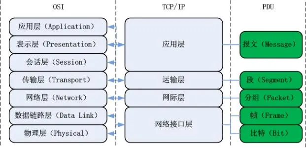
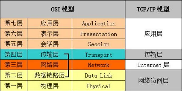
2. Hierarchical Structure of Computer Networks
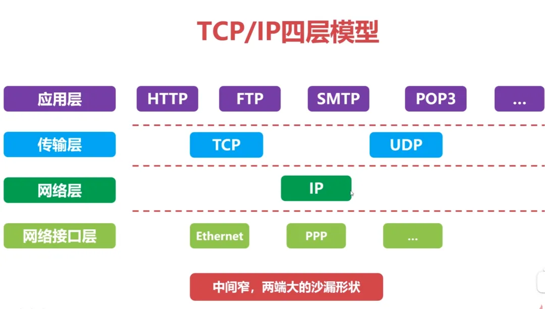
Comparison of TCP/IP Four-Layer Model and OSI Architecture:
3. Basic Principles of Hierarchical Structure Design
-
Each layer is independent of one another;
-
Each layer needs to have sufficient flexibility;
-
Complete decoupling between layers.
4. Performance Indicators of Computer Networks
Delay: transmission delay, propagation delay, queuing delay, processing delay;
Round Trip Time (RTT): The time taken for a data packet to travel from source to destination and back.
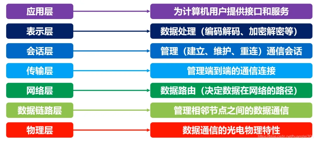
Function of the Physical Layer:
Connects different physical devices and transmits bit streams. This layer provides a reliable physical medium for data transmission for upper-layer protocols. In simple terms, the physical layer ensures that raw data can be transmitted over various physical media.
-
Repeater: Regenerates signals in the same local area network; ports must adhere to the same protocol; 5-4-3 rule: In a 10BASE-5 Ethernet, a maximum of 4 repeaters can be cascaded, with only 3 segments connecting hosts;
-
Hub: Regenerates and amplifies signals in the same local area network (multi-port repeater); half-duplex, cannot isolate collision domains or broadcast domains.
Basic Concept of a Channel: A channel is a medium for transmitting information in one direction; a communication circuit consists of a sending channel and a receiving channel.
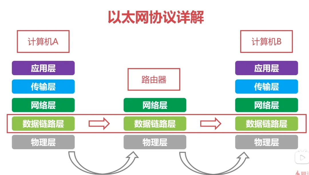
1. Overview of the Data Link Layer
The data link layer provides services to the network layer based on the services provided by the physical layer, with the most basic service being the reliable transmission of data from the network layer to the target machine’s network layer at adjacent nodes. The data link layer provides reliable transmission over unreliable physical media.
The functions of this layer include: physical addressing, framing of data, flow control, error detection of data, retransmission, etc.
Important Knowledge Points of the Data Link Layer:
-
The data link layer provides reliable data transmission for the network layer;
-
The basic data unit is a frame;
-
Main protocols: Ethernet protocol;
-
Two important device names: bridge and switch.
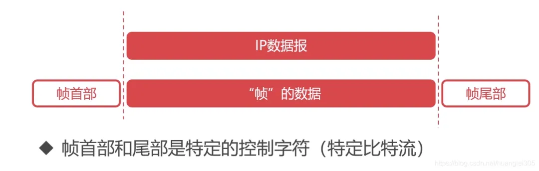
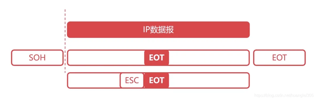
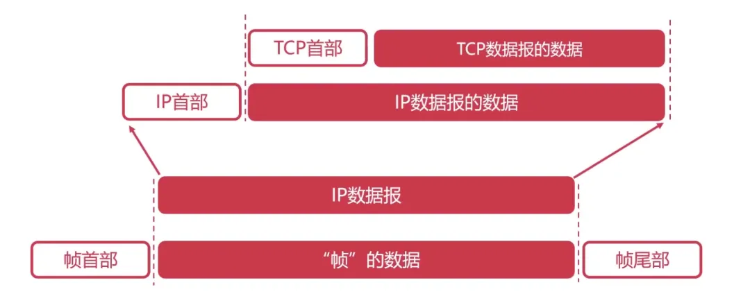
Encapsulation into Frames: “Frame” is the basic data unit of the data link layer:
Transparent Transmission: “Transparent” means that even if control characters are present in the frame data, they should be treated as if they do not exist. This is done by adding an escape character ESC before the control character.
2. Error Detection in the Data Link Layer
Error Detection: Parity check, Cyclic Redundancy Check (CRC)
-
Parity Check – Limitations: Errors cannot be detected when two bits are wrong.
-
Cyclic Redundancy Check: Generates a fixed-length checksum based on the data being transmitted or stored.
3. Maximum Transmission Unit (MTU)
The Maximum Transmission Unit (MTU) limits the size of data frames at the data link layer; data frame lengths are constrained by the MTU.
Path MTU: Determined by the minimum MTU in the link.
4. Detailed Explanation of the Ethernet Protocol
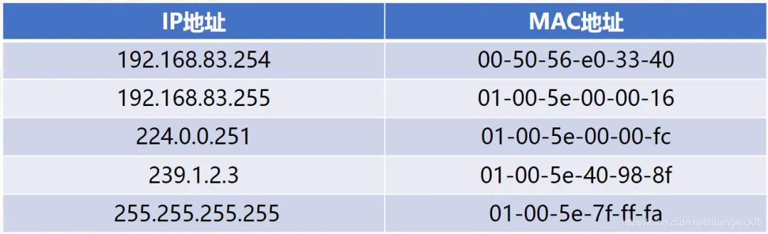
MAC Address: Each device has a unique MAC address, consisting of 48 bits, represented in hexadecimal.
Ethernet Protocol: A widely used local area network technology that is a protocol applied at the data link layer, allowing for data frame transmission between adjacent devices:
Classification of Local Area Networks:
-
First widely deployed high-speed local area network;
-
Fast data rates for Ethernet;
-
Low hardware costs for Ethernet, resulting in low network construction costs.
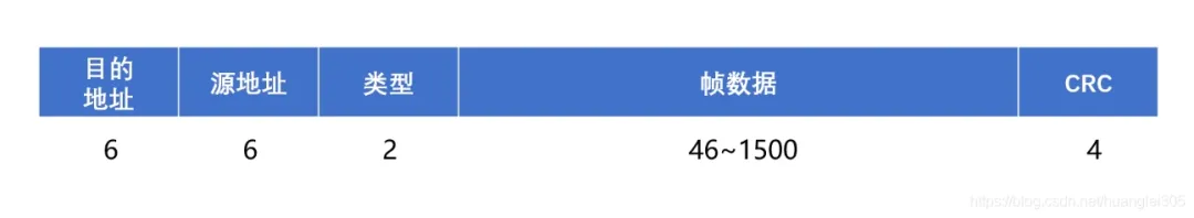
Ethernet Frame Structure:
-
Type: Identifies the upper layer protocol (2 bytes);
-
Destination and Source Address: MAC addresses (6 bytes each);
-
Data: Encapsulated upper layer protocol packets (46~1500 bytes);
-
CRC: Cyclic Redundancy Check (4 bytes);
-
Minimum Ethernet Frame: The minimum Ethernet frame is 64 bytes; excluding the data part of 18 bytes, the minimum data is 46 bytes.
MAC Address (Physical Address, Local Area Network Address)
The purpose of the network layer is to achieve transparent data transmission between two end systems, with specific functions including addressing and routing, connection establishment, maintenance, and termination. Data exchange technology is based on message switching (largely replaced by packet switching): using store-and-forward methods, where the data exchange unit is a message.
The network layer involves numerous protocols, among which the most important is the core protocol of TCP/IP – the IP protocol. The IP protocol is very simple, providing unreliable, connectionless transmission services. The main functions of the IP protocol include: connectionless datagram transmission, datagram routing, and error control.
Protocols used in conjunction with the IP protocol to achieve its functions include Address Resolution Protocol (ARP), Reverse Address Resolution Protocol (RARP), Internet Control Message Protocol (ICMP), and Internet Group Management Protocol (IGMP).
We will summarize specific protocols in the following sections, focusing on the network layer:
1) The network layer is responsible for routing packets between subnets. Additionally, the network layer can implement congestion control and internetworking functions;
2) The basic data unit is the IP datagram;
3) Major protocols included:
-
IP Protocol (Internet Protocol);
-
ICMP Protocol (Internet Control Message Protocol);
-
ARP Protocol (Address Resolution Protocol);
-
RARP Protocol (Reverse Address Resolution Protocol).
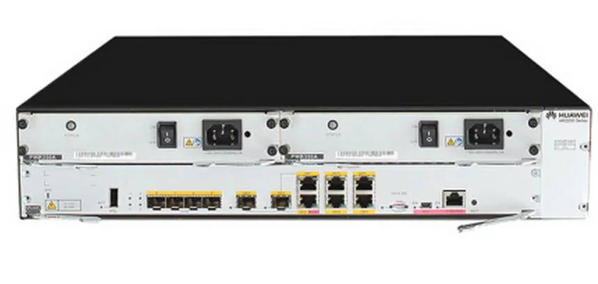
4) Important device: Router.
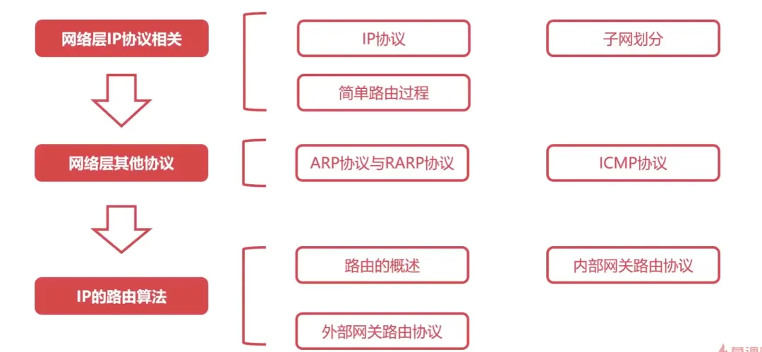
Router-related Protocols:
1. Detailed Explanation of the IP Protocol
The IP Internet protocol is the core protocol of the Internet network layer.
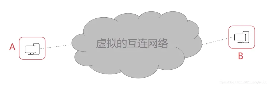
The emergence of virtual interconnected networks: The actual computer networks are complex; physical devices using the IP protocol mask the differences between physical networks; when hosts in the network connect using the IP protocol, there is no need to pay attention to network details, thus forming a virtual network.
The IP protocol transforms complex actual networks into a virtually interconnected network; it also resolves the issue of the transmission path of datagrams in the virtual network.
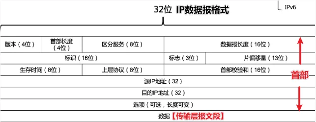
Here, the version refers to the version of the IP protocol, occupying 4 bits, such as IPv4 and IPv6;
The header length indicates the length of the IP header, occupying 4 bits, with a maximum value of 15;
The total length indicates the total length of the IP datagram, occupying 16 bits, with a maximum value of 65535;
TTL indicates the lifetime of the IP datagram in the network, occupying 8 bits;
The protocol indicates what specific data the IP data carries, such as TCP or UDP.
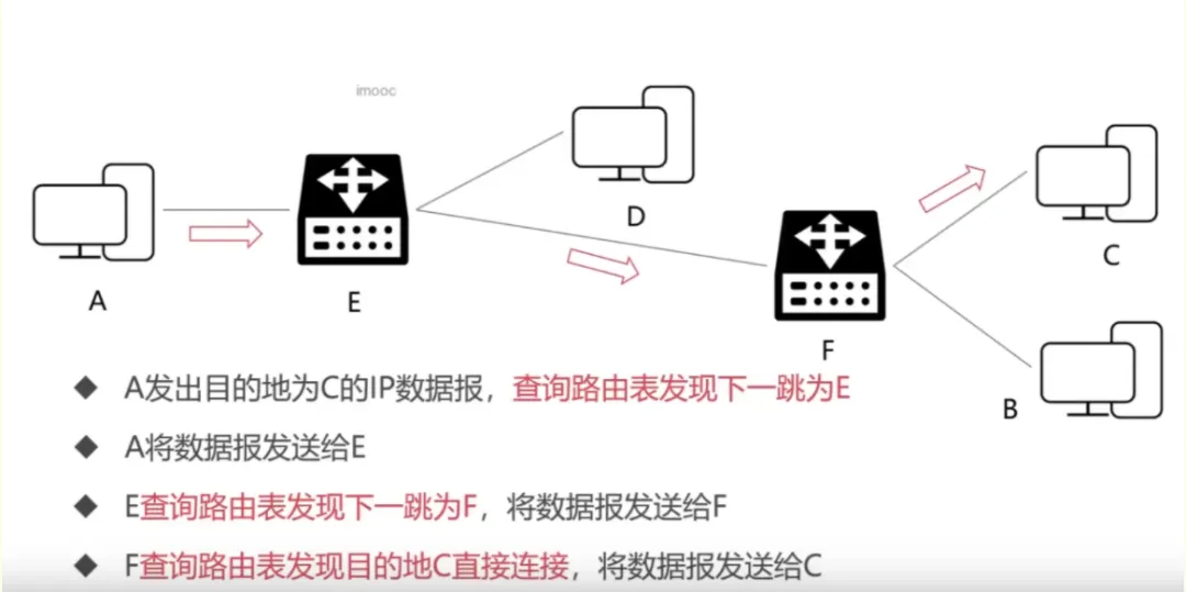
2. Forwarding Process of the IP Protocol
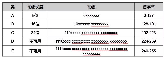
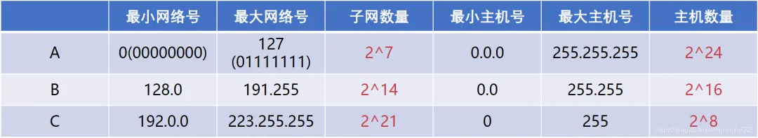
3. Subnetting of IP Addresses
Class A (8 network bits + 24 host bits), Class B (16 network bits + 16 host bits), Class C (24 network bits + 8 host bits) can be used to identify hosts or routers in the network, Class D addresses are used for group broadcast, and Class E is reserved addresses.
4. Network Address Translation (NAT) Technology
Used in a private network where multiple hosts access the Internet through a single public IP, reducing the consumption of IP addresses but increasing the complexity of network communication.
For IP datagrams leaving the internal network, replace their IP addresses with the legitimate public IP address owned by the NAT server, and record the replacement relationship in the NAT translation table;
For IP datagrams returning from the public Internet, retrieve the NAT translation table based on the destination IP address, replace the destination IP address with the retrieved internal private IP address, and then forward the IP datagram to the internal network.
5. ARP and RARP Protocols
Address Resolution Protocol (ARP): Provides dynamic mapping from the IP address of a network adapter to its corresponding hardware address. It can convert the 32-bit network layer address to the 48-bit MAC address of the data link layer.
ARP is plug-and-play; an ARP table is automatically established without requiring configuration by a system administrator.
RARP (Reverse Address Resolution Protocol) can convert the 48-bit MAC address of the data link layer to a 32-bit network layer address.
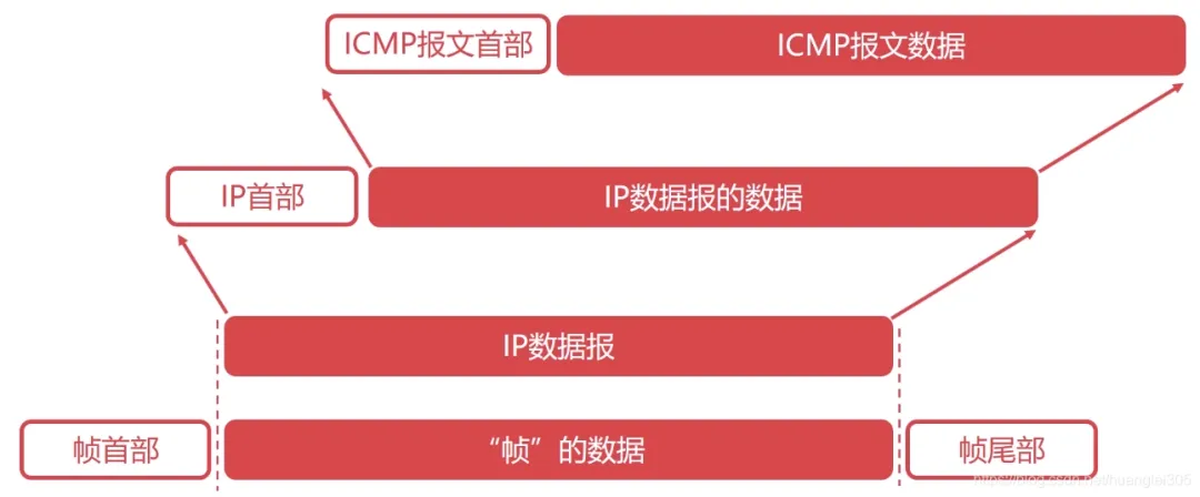
6. Detailed Explanation of the ICMP Protocol
The Internet Control Message Protocol (ICMP) can report error messages or abnormal situations, and ICMP messages are encapsulated in IP datagrams.
Applications of the ICMP Protocol:
-
Ping Application: Troubleshooting network issues;
-
Traceroute Application: Can probe the path that IP datagrams take through the network.
7. Overview of Routing in the Network Layer
Requirements for Routing Algorithms:
Correct and complete, computationally as simple as possible, adaptable to changes in the network, stable and fair.
A group of network devices under a management authority, with internal network autonomy, providing one or more entrances; the routing protocol within the autonomous system is an interior gateway protocol, such as RIP, OSPF; the routing protocol outside the autonomous system is an exterior gateway protocol, such as BGP.
Manually configured, high difficulty and complexity.
-
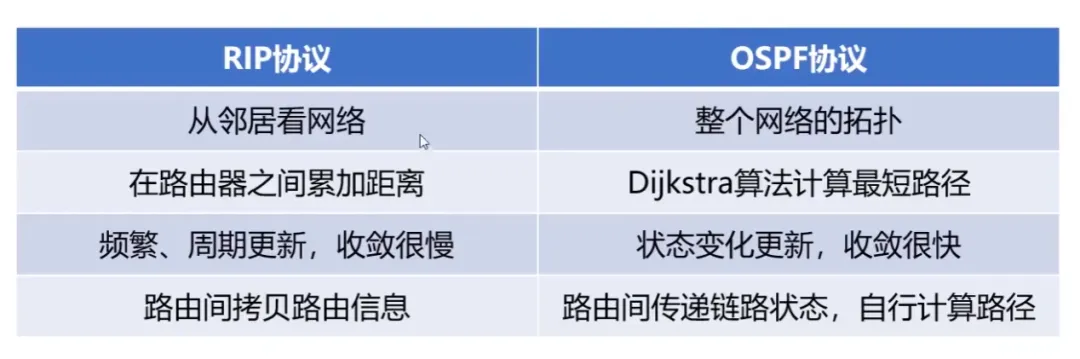
Link State Routing Algorithm (LS): Quickly converges by sending information to all neighboring routers; a global routing selection algorithm where each router constructs the entire network topology when calculating routes; uses Dijkstra’s algorithm to find the shortest path from the source to the destination network; Dijkstra’s algorithm;
-
Distance-Vector Routing Algorithm (DV): Slowly converges by sending information to all neighboring routers, may create loops; based on the Bellman-Ford equation (B-F equation).
8. RIP Protocol in Interior Gateway Routing Protocol
Routing Information Protocol (RIP) [Application Layer], based on the distance-vector routing algorithm, suitable for small networks in small autonomous systems; RIP messages are encapsulated in UDP datagrams.
Characteristics of the RIP Protocol:
-
RIP uses hop count as its metric (each router maintains distance records to every other router);
-
The cost of RIP is defined between the source router and the destination subnet;
-
The maximum diameter of the network for RIP is limited to 15 hops;
-
Exchanges all information with neighbors, actively every 30 seconds (broadcast).
9. OSPF Protocol in Interior Gateway Routing Protocol
Open Shortest Path First (OSPF) [Network Layer], based on the link state routing algorithm (Dijkstra’s algorithm), suitable for large autonomous systems and large networks, directly encapsulated in IP datagrams for transmission.
Advantages of OSPF Protocol:
-
-
Supports multiple equal-cost paths;
-
Supports differentiated cost metrics;
-
Supports unicast and multicast routing;
-
Comparison of RIP and OSPF (Routing Algorithms Determine Their Nature):
10. BGP Protocol in Exterior Gateway Routing Protocol
BGP (Border Gateway Protocol) [Application Layer]: A protocol running between autonomous systems, seeking a good route: initially exchanges all information, and subsequently only exchanges changes; BGP is encapsulated in TCP segments.
The first end-to-end layer, i.e., host-to-host. The transport layer is responsible for segmenting upper-layer data and providing end-to-end reliable or unreliable transmission.
Additionally, the transport layer must handle end-to-end error control and flow control issues.
The task of the transport layer is to optimally utilize network resources based on the characteristics of the communication subnet, providing functions for establishing, maintaining, and terminating transport connections between the session layers of two end systems, and ensuring reliable data transmission from end to end.
In this layer, the protocol data unit for information transmission is called a segment or message.
The network layer transmits data packets from the source node to the destination node based on network addresses, while the transport layer is responsible for reliably delivering data to the corresponding port.
Key Points about the Transport Layer:
-
The transport layer is responsible for segmenting upper-layer data and providing end-to-end reliable or unreliable transmission, as well as handling end-to-end error control and flow control issues;
-
Major protocols included: TCP protocol (Transmission Control Protocol), UDP protocol (User Datagram Protocol);
-
Important device: Gateway.
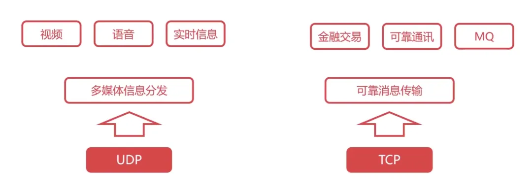
1. Detailed Explanation of the UDP Protocol
UDP (User Datagram Protocol) is a very simple protocol.
Characteristics of the UDP Protocol:
-
UDP is a connectionless protocol;
-
UDP cannot guarantee reliable delivery of data;
-
-
UDP has no congestion control;
-
UDP has very little header overhead.
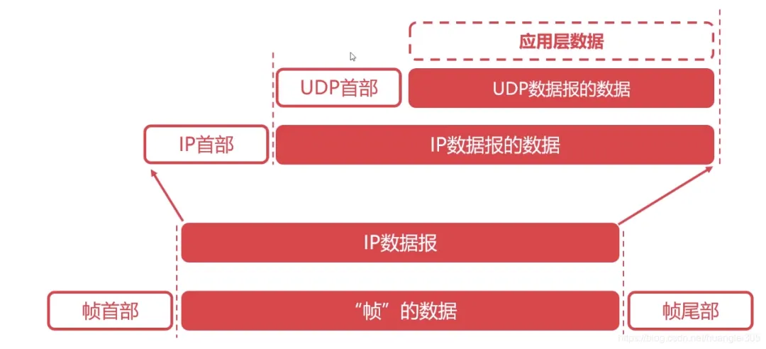
Header: 8B, four fields/2B [Source Port | Destination Port | UDP Length | Checksum] Data Field: Application Data.
2. Detailed Explanation of the TCP Protocol
TCP (Transmission Control Protocol) is a very complex protocol in computer networking.
Functions of the TCP Protocol:
-
Segments and reassembles application layer messages;
-
Multiplexes and demultiplexes at the application layer;
-
Implements end-to-end flow control;
-
-
Transport layer addressing;
-
Performs error detection on received messages (both header and data parts are checked);
-
Ensures end-to-end reliable data transmission control between processes.
Characteristics of the TCP Protocol:
-
TCP is a connection-oriented protocol;
-
TCP is a byte stream-oriented protocol;
-
A TCP connection has two ends, i.e., point-to-point communication;
-
TCP provides reliable transmission services;
-
TCP protocol provides full-duplex communication (each TCP connection can only be one-to-one).
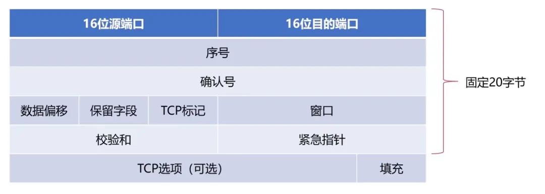
Structure of TCP Segments:
Maximum Segment Length: The maximum length of application layer data encapsulated in the segment.
-
Sequence Number Field: The TCP sequence number is assigned to each byte of application layer data;
-
Acknowledgment Number Field: The expected sequence number of the byte to be received from the other party, i.e., the byte corresponding to this sequence number has not yet been received. Identified by ack_seq;
-
The minimum length of the TCP segment header is 20B, and the maximum is 60 bytes. However, the length must be a multiple of 4B.
3. Basic Principles of Reliable Transmission
-
Possible issues in data transmission over unreliable transmission channels: bit errors, out-of-order delivery, retransmission, loss;
-
Measures taken to achieve reliable data transmission over unreliable channels.
Error Detection: Utilizing coding to detect bit errors during data packet transmission.
Acknowledgment: The receiver provides feedback on the reception status to the sender.
Retransmission: The sender resends data that the receiver did not correctly receive.
Sequence Number: Ensures that data is submitted in order.
Timer: Addresses data loss issues.
Stop-and-Wait Protocol: The simplest reliable transmission protocol, but it has low channel utilization.
Continuous ARQ (Automatic Repeat reQuest): Sliding window + cumulative acknowledgment, significantly improves channel utilization.
Reliable Transmission of TCP Protocol:
Based on the continuous ARQ protocol, in some cases, the efficiency of retransmission is not high, and some bytes that have already been successfully received may be retransmitted.
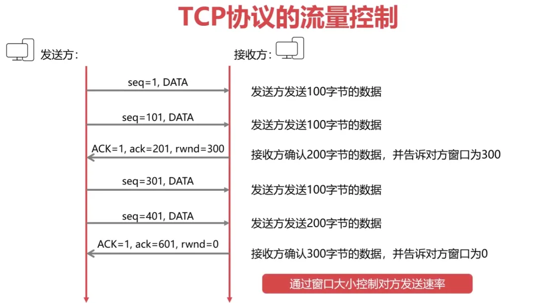
Flow Control of TCP Protocol:
Flow Control: Prevents the sender from sending data too quickly; the TCP protocol uses a sliding window to implement flow control.
4. Congestion Control of TCP Protocol
Difference between Congestion Control and Flow Control:
Flow control considers the control of communication volume point-to-point, while congestion control considers the entire network and is a global consideration. Methods of congestion control: Slow Start Algorithm + Congestion Avoidance Algorithm.
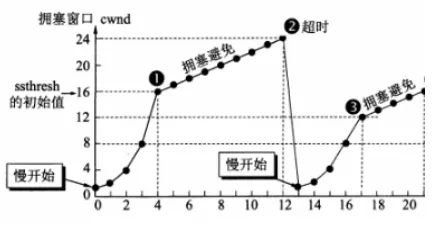
Slow Start and Congestion Avoidance:
-
In [Slow Start], the congestion window grows exponentially from 1;
-
When the threshold is reached, it enters [Congestion Avoidance], growing by +1;
-
In the event of a [Timeout], the threshold is halved (cannot be < 2);
-
Then starts from [Slow Start], the congestion window grows exponentially from 1.
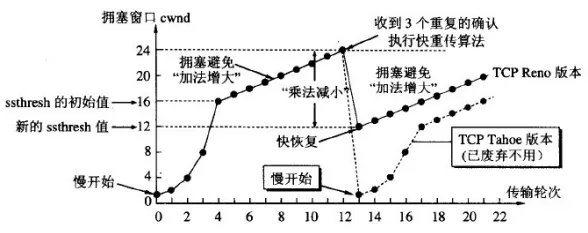
Fast Retransmit and Fast Recovery:
-
If the sender receives three duplicate ACKs in a row, it performs [Fast Retransmit] without waiting for the timer to expire;
-
Performs [Fast Recovery], the threshold is set to half of the current cwnd (cannot be < 2), and enters [Congestion Avoidance] from this new ssthresh point.
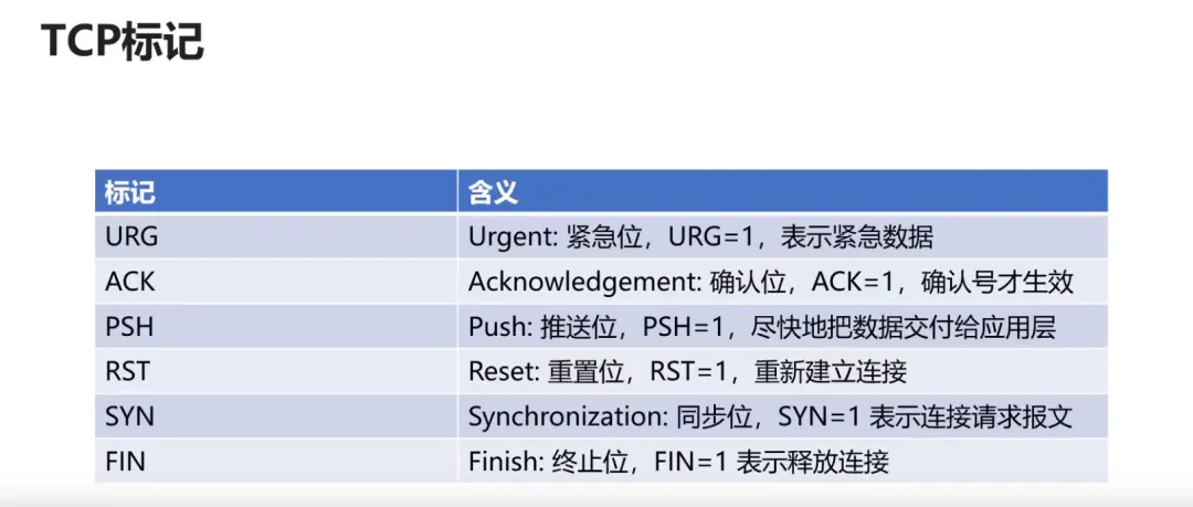
5. TCP Connection Establishment with Three-Way Handshake (Important)
Commands Used in TCP Three-Way Handshake:
Common Interview Question: Why is Three-Way Handshake Necessary?
-
First Handshake: The client sends a request, at which point the server knows the client can send;
-
Second Handshake: The server sends an acknowledgment, at which point the client knows the server can send and receive;
-
Third Handshake: The client sends an acknowledgment, at which point the server knows the client can receive.
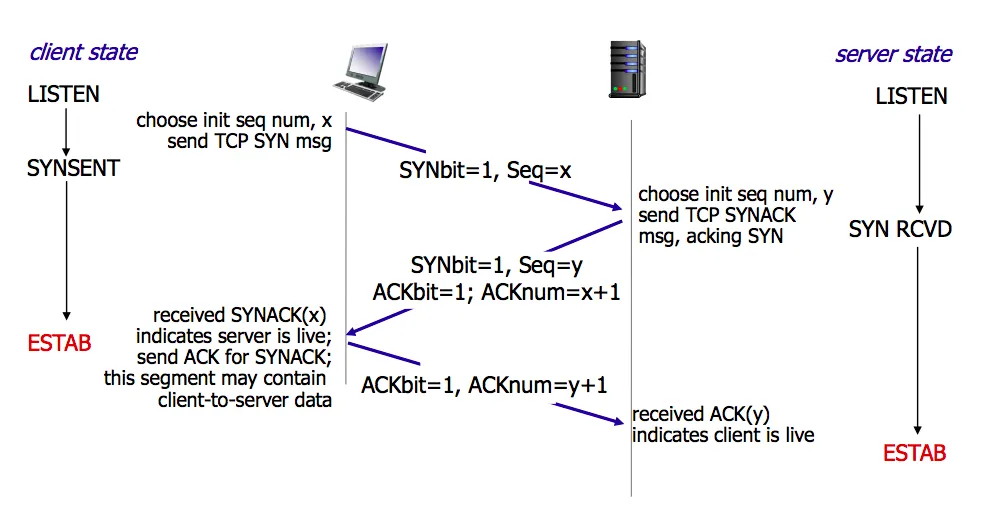
Establishing Connection (Three-Way Handshake):
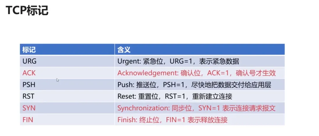
First: The client sends a connection request segment to the server, establishing a connection request control segment (SYN=1), indicating that the sequence number of the first data byte in the transmitted segment is x, representing the sequence number for the entire segment (seq=x); the client enters the SYN_SEND (synchronizing sending state);
Second: The server sends back an acknowledgment segment, agreeing to establish a new connection (SYN=1), with the acknowledgment number field valid (ACK=1), indicating that the server tells the client the segment sequence number is y (seq=y), indicating that the server has received the client’s segment with sequence number x and is prepared to accept the client’s segment with sequence number x+1 (ack_seq=x+1); the server transitions from LISTEN to SYN_RCVD (synchronizing received state);
Third: The client acknowledges the same connection to the server. The acknowledgment number field is valid (ACK=1), and the client’s segment sequence number is x+1 (seq=x+1), expecting to receive the server’s segment with sequence number y+1 (ack_seq=y+1); when the client sends ack, the client enters the ESTABLISHED state; when the server receives the client’s ack, it also enters the ESTABLISHED state; the third handshake may carry data.
6. TCP Connection Termination with Four-Way Handshake (Important)
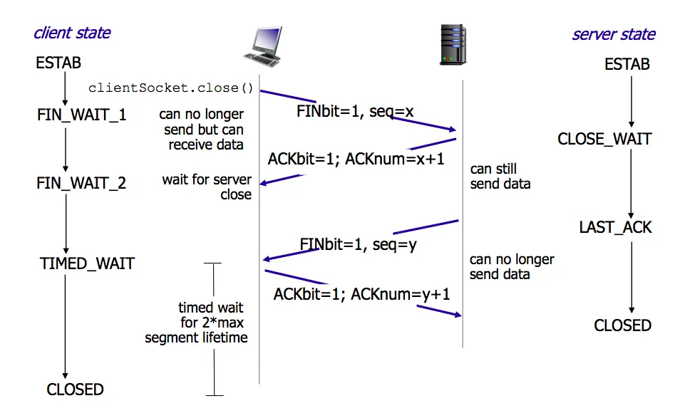
Releasing Connection (Four-Way Handshake)
First: The client sends a release connection segment to the server, indicating that the sender has finished sending data, requesting to release the connection (FIN=1), with the sequence number of the first data byte being x (seq=x); the client’s state transitions from ESTABLISHED to FIN_WAIT_1 (waiting for termination state 1);
Second: The server sends an acknowledgment segment to the client, with the acknowledgment number field valid (ACK=1), indicating that the sequence number of the data sent by the server is y (seq=y), and the server expects to receive the client’s data sequence number of x+1 (ack_seq=x+1); the server’s state transitions from ESTABLISHED to CLOSE_WAIT (waiting for closure); the client transitions from FIN_WAIT_1 to FIN_WAIT_2 after receiving the ACK segment;
Third: The server sends a release connection segment to the client, requesting to release the connection (FIN=1), with the acknowledgment number field valid (ACK=1), indicating that the server expects to receive the client’s data sequence number of x+1 (ack_seq=x+1); indicating that the first byte sequence number transmitted by itself is y+1 (seq=y+1); the server transitions from CLOSE_WAIT to LAST_ACK (final acknowledgment state);
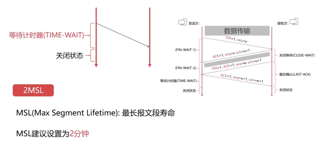
Fourth: The client sends an acknowledgment segment to the server, with the acknowledgment number field valid (ACK=1), indicating that the data sequence number transmitted by the client is x+1 (seq=x+1), indicating that the client expects to receive the server’s data sequence number of y+1+1 (ack_seq=y+1+1); the client’s state transitions from FIN_WAIT_2 to TIME_WAIT, waiting for 2MSL time, and then transitions to CLOSED state; the server transitions to CLOSED after receiving the final ACK.
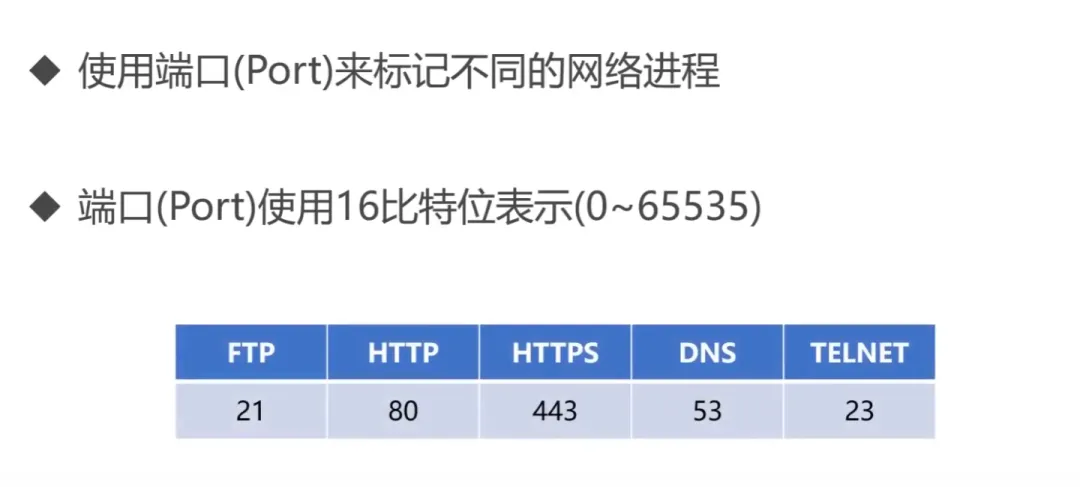
Provides an interface for operating systems or network applications to access network services. Key points of the application layer:
-
The basic unit of data transmission is the message;
-
Major protocols included: FTP (File Transfer Protocol), Telnet (Remote Login Protocol), DNS (Domain Name System), SMTP (Simple Mail Transfer Protocol), POP3 (Post Office Protocol), HTTP (Hypertext Transfer Protocol).
1. Detailed Explanation of DNS
DNS (Domain Name System) [C/S, UDP, Port 53]: Solves the problem of complex IP addresses that are difficult to remember, storing and completing the mapping of domain names to IP addresses within its jurisdiction.
Order of Domain Name Resolution:
-
-
Check the local hosts file;
-
-
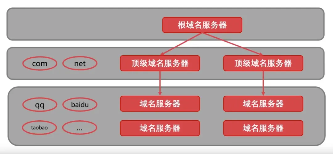
Check DNS servers (local domain, top-level domain, root domain) -> iterative resolution, recursive query.
IP -> DNS service -> easily memorable domain name.
Domain names consist of dots, letters, and numbers, divided into top-level domains (com, cn, net, gov, org), second-level domains (baidu, taobao, qq, alibaba), and third-level domains (www) (12-2-0852).
2. Detailed Explanation of DHCP Protocol
DHCP (Dynamic Host Configuration Protocol) is a local area network protocol that is an application layer protocol using UDP. Its function is to automatically assign IP addresses to users temporarily connecting to the local area network.
3. Detailed Explanation of HTTP Protocol
File Transfer Protocol (FTP): Control connection (port 21): Transmits control information (connection, transmission requests) in 7-bit ASCII format. The connection remains open throughout the session.
HTTP (HyperText Transfer Protocol) [TCP, port 80]: A reliable data transmission protocol where the browser establishes a TCP connection with the server before sending and receiving messages; HTTP uses a TCP connection method (HTTP itself is connectionless).
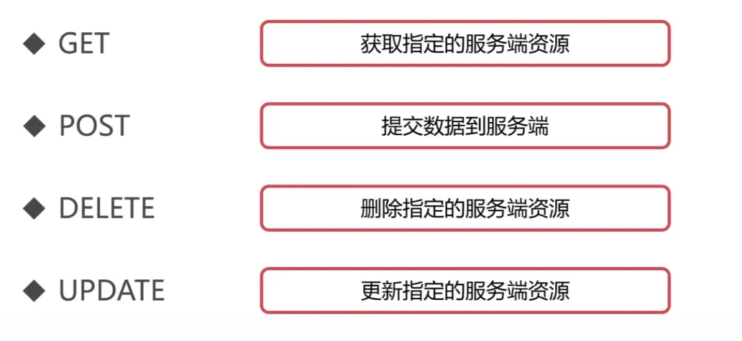
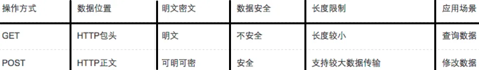
HTTP Request Message Methods:
-
GET: Requests specified page information and returns the entity body;
-
POST: Submits data to the specified resource for processing;
-
DELETE: Requests the server to delete the specified page;
-
HEAD: Requests to read the header of the URL identifier, returning only the message header;
-
OPTIONS: Requests information about some options;
-
PUT: Stores a document under the specified URL.
1) Structure of HTTP Work
2) Detailed Explanation of HTTPS Protocol
HTTPS (Secure) is a secure version of the HTTP protocol, using port 443. Based on the HTTP protocol, it provides encrypted processing of data, verifies the identity of the other party, and protects data integrity.
In fact, much of the content discussed here has been learned during school, but if not used, it is basically forgotten. It is sufficient to accumulate knowledge purposefully, so that when needed, the source can be identified.
If you find this article somewhat helpful, please do not hesitate to click the “Like” and “View” at the end of the article or share it directly to your circle of friends.
Recently Updated Articles:
“Exploring the Essence of Architecture”
“Practical Scenarios for Optimizing Group By Statements in MySQL”
“Optimization Scenarios for Rewriting Subqueries”
“Understanding the Composition of Road Bike Wheel Sets”
“MySQL’s ‘Row Size Too Large’ Error Scenario”
“China’s Team ‘Own’ World Cup“
“You Don’t Know About CR7’s Siu Celebration“
“15 Key Concepts of Architecture Design”
“Universal Studios Osaka Pitfall Guide and Strategy”
“A Classic Paper on Oracle RAC Cache Fusion”
“The Shock of ‘Red Alert’ Game Open Source Code“
Article Classification and Index:
“Classification and Index of 1500 Articles in Public Account”