

1 TCP/IP Layered Model
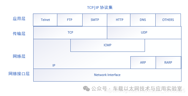
The TCP/IP four-layer model consists of the application layer, transport layer, network layer, and network interface layer (data link layer) from top to bottom.
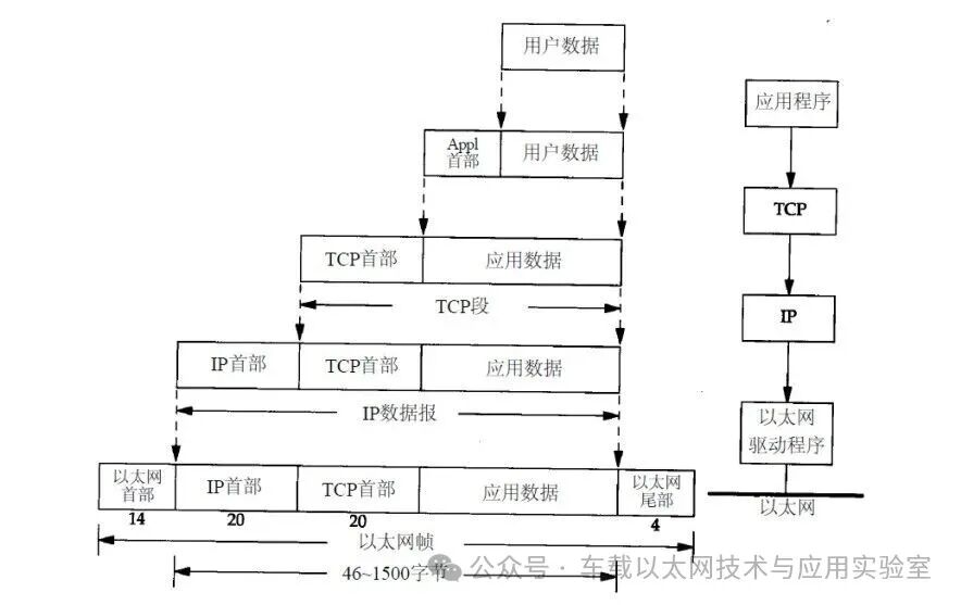
Data at the transport layer is referred to as: segment (TCP) or datagram (UDP).
Data at the network layer is referred to as: packet.
Data at the network interface layer is referred to as: frame.
The physical network cable actually transmits a bit stream.
Data reception flow:
Network cable —> Network card —> Network card driver —> MAC —> IP —> TCP/UDP —> System call —> Application layer
2 TCP Three-Way Handshake / Four-Way Handshake
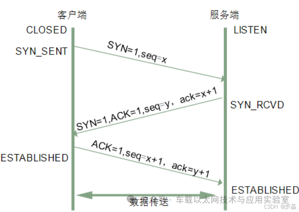
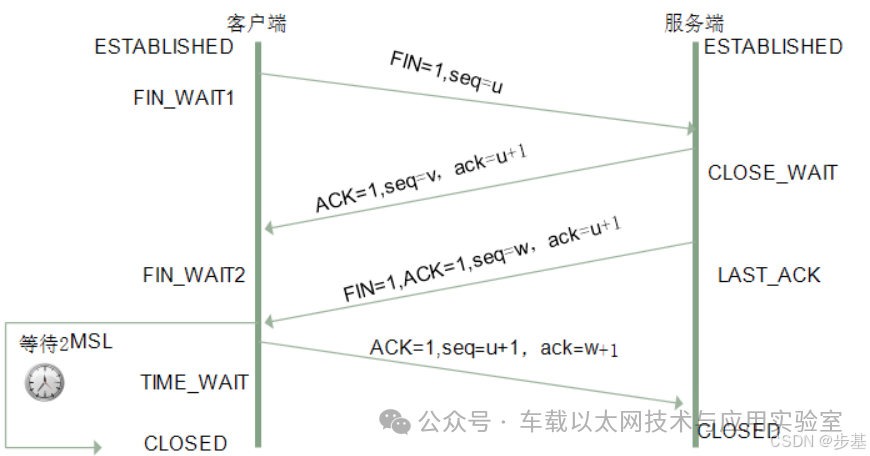
The client and server initially are in the CLOSED and LISTEN states, respectively, and both are in the ESTABLISHED state after a successful connection.
The SYN flag starts the connection establishment, ACK=1 indicates the acknowledgment bit, and ack=x+1 indicates the acknowledgment number for seq=x. Note the case sensitivity.
3 TCP Data Frame Format
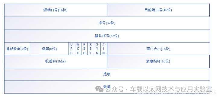
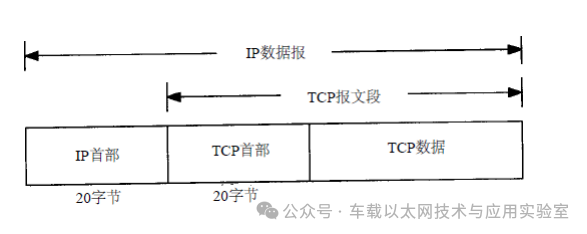
TCP (Transmission Control Protocol) is a connection-oriented protocol (a TCP connection is established through a three-way handshake, creating a session between hosts), reliable (TCP ensures data delivery through acknowledgment and in-order delivery), and a byte-stream-based transport layer communication protocol. However, TCP transmission is relatively slow, has slightly higher overhead, and only supports point-to-point communication. When the application layer sends an 8-byte data stream for inter-network transmission to the TCP layer, TCP segments the data stream into appropriately sized packets. The maximum segment size (MSS) is usually limited by the maximum transmission unit (MTU) of the data link layer of the network to which the computer is connected. Afterward, TCP passes the packet to the IP layer, which is responsible for delivering the packet to the receiving entity’s TCP layer through the network.
/* TCP Header Definition, total of 20 bytes */
typedef struct _TCP_HEADER
{
short m_sSourPort; // Source port number 16 bit
short m_sDestPort; // Destination port number 16 bit
unsigned int m_uiSeqNum; // Sequence number 32 bit
unsigned int m_uiAcknowledgeNum; // Acknowledgment number 32 bit
short m_sHeaderLenAndFlag; // First 4 bits: TCP header length; middle 6 bits: reserved; last 6 bits: flags
short m_sWindowSize; // Window size 16 bit
short m_sCheckSum; // Checksum 16 bit
short m_surgentPointer; // Urgent data offset 16 bit
} __attribute__((packed)) TCP_HEADER, *PTCP_HEADER;
Source port: 2 bytes, a 16-bit number greater than 1023, randomly chosen by the user process of the TCP application.
Destination port: 2 bytes, indicating the port number used by the receiver, generally specified by the application.
Sequence number: 4 bytes, used to identify the byte stream of data sent from the TCP source to the TCP destination. It indicates the sequence number of the first data byte in this segment. If the byte stream is viewed as a unidirectional flow between two applications, TCP counts each byte with the sequence number, which is a 32-bit unsigned number that wraps around to 0 after reaching 2^32-1. For example, if we receive a datagram with sq (sequence number) = 0 and the content is 20 bytes, the next datagram’s sq should be 21. When establishing a new connection, the SYN flag is set to 1, and the sequence number field contains the initial sequence number (ISN) chosen by this host.
Acknowledgment number: 4 bytes, contains the next sequence number that the sender expects to receive. Therefore, the acknowledgment number should be the last successfully received data byte’s sequence number plus 1. For example, if we receive a datagram with sq = 0 and the content is 20 bytes, our ack (acknowledgment number) should be 21, indicating that the datagram with sq=0 and content of 20 bytes has been received, and we expect to receive the datagram with sq=21 next. The acknowledgment number field is only valid when the ACK flag is set to 1.
Header length: 4 bits, indicates the number of 32-bit words in the header, necessary because the length of optional fields is variable. This field occupies 4 bits, meaning TCP can have a maximum header length of 60 (15*4) bytes.
Reserved: 6 bits, reserved for future use, must currently be set to 0.
Control bits: 6 bits, including
URG: set to 1 indicates the urgent pointer is valid, set to 0 ignores the urgent pointer value.
ACK: set to 1 indicates the acknowledgment number is valid, set to 0 indicates the message does not contain acknowledgment information, ignoring the acknowledgment number field.
PSH: set to 1 indicates that the data has the PUSH flag, meaning there is no more data to send in the sender’s buffer, instructing the receiver to deliver this segment to the application layer as soon as possible without waiting for the buffer to fill up.
RST: used to reset a connection that has encountered an error due to host crashes or other reasons. It can also be used to reject illegal segments and connection requests. Generally, if a packet with RST set to 1 is received, some issue has occurred.
SYN: synchronize sequence number, set to 1 indicates a connection request, used to establish a connection and synchronize sequence numbers.
FIN: used to release a connection, set to 1 indicates that the sender has no more data to send, i.e., closing its data stream.
Window size: 2 bytes, indicates the number of bytes that the source can receive starting from the acknowledgment number, i.e., the size of the source’s receive window. The window size is a 16-bit field, so the maximum window size is 2^16-1.
Checksum: 2 bytes, used to calculate the checksum for the entire TCP segment (including the TCP header, TCP data, and pseudo-header). This is a mandatory field, required to be calculated and stored by the sender, and verified by the receiver (the receiver’s value must match the sender’s for the data to be considered valid).
Urgent pointer: 2 bytes, a positive offset, added to the value in the sequence number field to indicate the sequence number of the last byte of urgent data. The urgent mode of TCP is a way for the sender to send urgent data to the other end, and the urgent pointer is only valid when the URG flag is set to 1.
Options: n*4 bytes, common optional fields include Maximum Segment Size (MSS). Each connection typically specifies this option in the first segment of communication (the segment with the SYN flag set for connection establishment), indicating the maximum length of the segment that can be received. The option length does not have to be a multiple of 32 bits, so padding bits are added to make the total length a multiple of 32 bits.
Data: variable length, data encapsulated by the upper layer protocol.
4 TCP Sliding Window
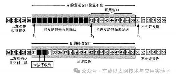
Bytes within the sending window are allowed to be sent, and bytes within the receiving window are allowed to be received. If the bytes on the left side of the sending window have been sent and acknowledged, the sending window slides right by a certain distance until the first byte on the left is not in the sent and acknowledged state; the sliding of the receiving window is similar, where the left side bytes that have been sent, acknowledged, and delivered to the host will slide the receiving window to the right.
The receiving window will only acknowledge the last byte that arrived in order. For example, if the received bytes are {31, 34, 35}, where {31} arrived in order, while {34, 35} did not, only byte 31 will be acknowledged. Once the sender receives an acknowledgment for a byte, it knows that all bytes before that have been received.
TCP Flow Control and Congestion Control
TCP flow control is implemented using the sliding window mechanism, primarily controlling the sending rate of the sender to ensure the receiver can keep up. The receiver will include its receive window size in the returned data to control the sender’s data transmission. Congestion control: Congestion control prevents too much data from being injected into the network, which can overload routers or links in the network.
The window field in the acknowledgment message sent by the receiver can be used to control the sender’s window size, thereby affecting the sender’s sending rate. Setting the window field to 0 means the sender cannot send data.
In practice, to avoid this issue, the sender host will occasionally send a data segment called window probe, which contains only one byte to obtain the latest window size information.
The difference between the two: flow control is to prevent congestion. For example, in traffic, traffic police and traffic lights are flow control; when congestion occurs, how to disperse is congestion control. Flow control refers to point-to-point communication volume control, while congestion control is global, involving all hosts and factors that degrade network performance.
Two methods for solving congestion:
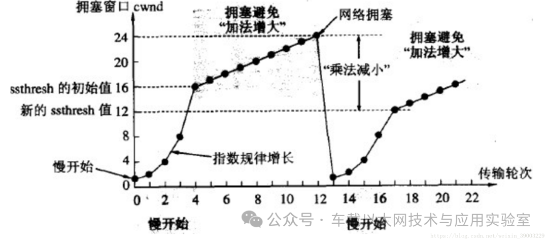
The principle of controlling the congestion window on the sender’s side is: as long as there is no congestion in the network, the congestion window will increase to send more packets. However, once congestion occurs, the congestion window will decrease to reduce the number of packets injected into the network.
The sender needs to maintain a state variable called the congestion window (cwnd). Note the difference between the congestion window and the sender’s window: the congestion window is just a state variable, while the actual amount of data the sender can send is determined by the sender’s window.
Slow Start + Congestion Avoidance
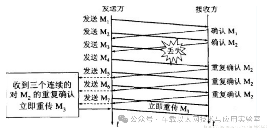
Fast Retransmit + Fast Recovery
5 UDP Data Frame Format
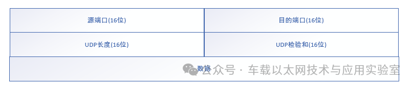
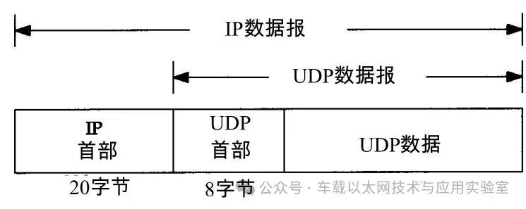
UDP (User Datagram Protocol) is a protocol used in networks to handle data packets, similar to TCP, but it is unreliable (does not require acknowledgment, does not order packets, does not perform flow control, and may experience loss, duplication, or out-of-order issues), connectionless (does not establish a session between hosts), and operates at the transport layer of the OSI model, above the IP protocol. Due to the unreliability of UDP transmission, its frame structure is simpler, and it has high processing and sending rates with low overhead, supporting point-to-point and one-to-many communications. It is often used for audio, video, and general data transmission protocols, as losing one or two packets occasionally does not significantly affect the reception results.
/* UDP Header Definition, total of 8 bytes */
typedef struct _UDP_HEADER
{
unsigned short m_usSourPort; // Source port number 16 bit
unsigned short m_usDestPort; // Destination port number 16 bit
unsigned short m_usLength; // Packet length 16 bit
unsigned short m_usCheckSum; // Checksum 16 bit
} __attribute__((packed)) UDP_HEADER, *PUDP_HEADER;
Source port: 16 bit (2 bytes), a 16-bit number greater than 1023, randomly chosen by the user process of the UDP application.
Destination port: 16 bit (2 bytes), indicating the port number used by the receiver, generally specified by the application.
Data length: 16 bit (2 bytes), indicating the total byte length of the UDP header and UDP data.
Checksum field: 16 bit (2 bytes), used to check the UDP header and UDP data. Unlike TCP, this field is optional, while the TCP segment must include a checksum field.
Data: variable length, data encapsulated by the upper layer protocol.
6 IP Data Frame Format
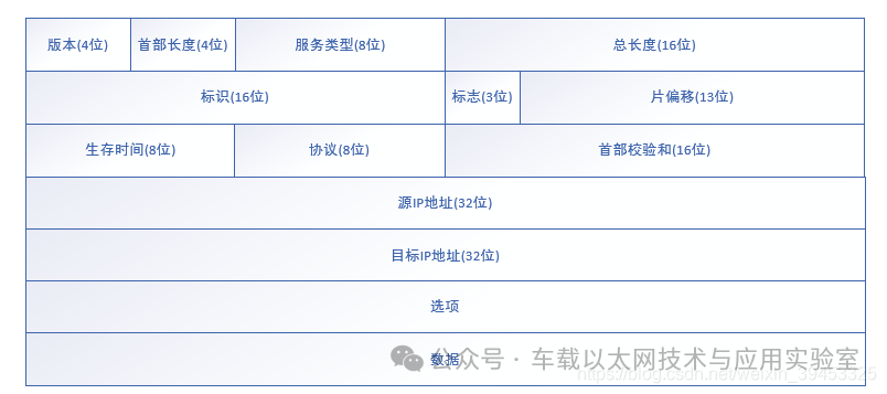
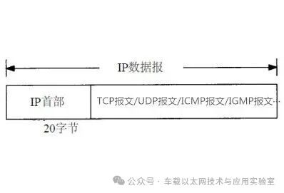
The IP protocol is the core protocol in the TCP/IP protocol suite, providing unreliable, connectionless service, relying on other layer protocols for error control. In local area networks, the IP protocol is often encapsulated in Ethernet frames, while all TCP, UDP, ICMP, and IGMP data are transmitted encapsulated in IP datagrams.
/* IP Header Definition, total of 20 bytes */
typedef struct _IP_HEADER
{
char m_cVersionAndHeaderLen; // First 4 bits: version information; last 4 bits: header length
char m_cTypeOfService; // Type of service 8 bits
short m_sTotalLenOfPacket; // Packet length
short m_sPacketID; // Packet identifier
short m_sSliceinfo; // Fragmentation information
char m_cTTL; // Time to live
char m_cTypeOfProtocol; // Protocol type
short m_sCheckSum; // Checksum
unsigned int m_uiSourIp; // Source IP
unsigned int m_uiDestIp; // Destination IP
} __attribute__((packed)) IP_HEADER, *PIP_HEADER;
Version: 4 bits, indicates the version number of the IP protocol implementation, currently generally IPv4, which is 0100, and IPv6 is 0110. This field ensures compatibility between devices that may run different IP versions.
Header length: 4 bits, defines the length of the IP header in 32-bit words, including optional fields. The minimum value for this field is 5 (standard header length), which is 5*32=160 bits = 20 bytes, and the maximum value is 15 (with extensions), which is 15*32 = 480 bits = 60 bytes.
Type of service: 8 bits, used to carry information about the quality of service characteristics. The type of service field declares how the datagram can be processed when transmitted by the network system. The first 3 bits are precedence subfields (now ignored, not adopted by various terminals). The 8th bit is reserved. The 4th to 7th bits represent delay, throughput, reliability, and cost, respectively. When they are set to 1, they represent the minimum delay, maximum throughput, highest reliability, and minimum cost. Only one of these 4 bits can be set to 1, and they can all be 0, indicating normal service. In most cases, this type of service will be ignored.
Total length: 16 bits, indicates the length of the entire datagram in bytes, with a maximum length of 2^16 bytes.
Identifier: 16 bits, uniquely identifies each datagram sent by the host. The IP software maintains a counter in memory, which increments by 1 for each generated datagram and assigns this value to the identifier field. However, this “identifier” is not a sequence number, as IP is a connectionless service, and there is no issue of ordered reception. If a datagram must be fragmented due to exceeding the network’s MTU (maximum transmission unit), the value of this identifier field will be copied to all fragments, allowing them to be correctly reassembled into the original datagram.
Flags: 3 bits, including RF, DF, MF, currently only DF and MF are effective. DF (don’t fragment), when set to 0 indicates fragmentation is allowed, when set to 1 indicates fragmentation is not allowed. MF (more fragment), when set to 0 indicates this segment is the last segment, when set to 1 indicates there are more fragments to follow.
Fragment offset: 13 bits, indicates the relative position of a segment in the original packet after fragmentation. In other words, it indicates where this fragment starts relative to the user field. The offset is measured in units of 8 bytes (3 bits are occupied by flags), meaning each fragment’s length must be a multiple of 8 bytes (64 bits).
Time to live: 8 bits, used to set the maximum number of routers the datagram can pass through, set by the source host sending the data, usually 32, 64, 128, etc. The value decreases by 1 for each router it passes through, and when it reaches 0, the datagram is discarded.
Protocol: 8 bits, indicates which upper-layer protocol is encapsulated in the IP data field, common ones include ICMP (1), IGMP (2), TCP (6), UDP (17).
Header checksum: 16 bits, filled with the checksum code calculated based on the IP header. The calculation method is to sum the binary complement of each 16 bits in the header, excluding the data field.
Source IP address: 32 bits, the source IP address.
Destination IP address: 32 bits, the destination IP address.
Options: n*32 bits, used to define optional fields such as recording paths, timestamps, etc., but these options are rarely used, and not all hosts and routers support them. The length of optional fields must be a multiple of 32 bits, and if not, padding with 0 is required to meet this length requirement. The length of options can be obtained from IHL (header length).
Data: variable length, but limited by the maximum length of the datagram 2^16, which is the data to be transmitted in the datagram, a complete higher-layer message or a fragment of a message.
7 Ethernet Frame Format

In the data link layer, Ethernet is the most widely used, and due to historical reasons, there are multiple versions of Ethernet frames. Here, we adopt the IEEE 802.3 Ethernet frame format.
Leading code: 7 bytes, used for synchronizing the sending and receiving rates during data transmission.
SFD: Start Frame Delimiter, 1 byte, used to indicate the start of an Ethernet frame.
Destination MAC address: 6 bytes, indicating the receiver of the frame.
Source MAC address: 6 bytes, indicating the sender of the frame.
Length: 2 bytes, indicating the length of the data field of the frame, but does not represent that the data field length can reach 2^16 bytes.
Type: 2 bytes, indicating the protocol type of the data in the frame, for example, the IP protocol in IPv4 uses 0x0800.
Data and padding: 46~1500 bytes, containing the data passed down from the upper layer protocol. If the length of the frame is less than 64 bytes after adding the data field, padding is added to reach 64 bytes.
Checksum: 4 bytes, a method for the receiving network card (mainly to check the data and padding fields) to determine whether there was an error in transmission. If an error is found, this frame is discarded. The most popular algorithm for checksum (FCS) is cyclic redundancy check (CRC).
8 CRC Calculation Example
Assuming the chosen CRC generating polynomial is to find the CRC checksum for the binary sequence 10110011. Below is the specific calculation process:
① Convert the polynomial into a binary sequence. It is known that the binary has five bits, with the 4th, 3rd, and 0th bits being 1, so the sequence is 11001.
② The polynomial has 5 bits, so add 5-1 zeros to the end of the data frame, making the data frame 101100110000, then use modulo 2 division by the divisor 11001 to get the remainder.
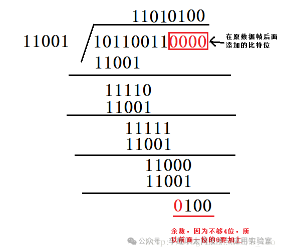
③ Add the calculated CRC checksum to the end of the original frame, making the actual data frame 101100110100, and then send this data frame to the receiving end.
④ The receiving end receives the data frame, performs modulo 2 division by 11001, and checks whether the remainder is 0. If it is 0, it indicates that the data frame has no errors.
Disclaimer: We respect originality and emphasize sharing; the text and images are copyrighted by the original authors. The purpose of reproduction is to share more information and does not represent our position. If your rights are infringed, please contact us promptly, and we will delete it as soon as possible. Thank you!
Original link:
https://blog.csdn.net/wangbuji/article/details/117525465