What Are Transport Networks, Core Networks, Transmission Networks, and Access Networks?
Today, I will mainly talk about carrier networks, their evolution, and technological trends to help beginners understand the development of networks, services, and technology.
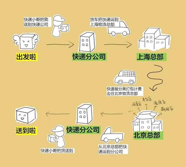
Before we delve into the knowledge, let me share a story about sending a package:
I want to send a package from Shanghai to a friend in Beijing ( ̄_, ̄ )
With this story in mind, let’s understand what a network is:
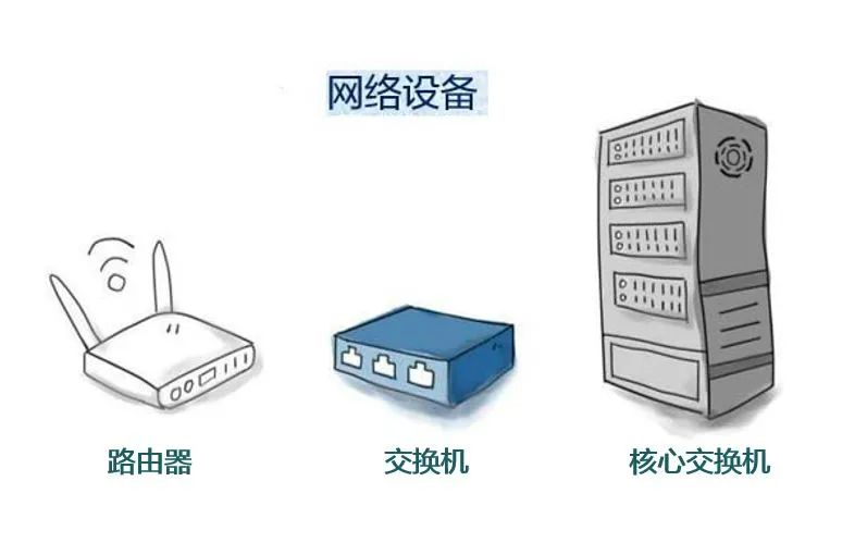
If you have encountered networks before, you must be familiar with them. Let’s call them network devices for now. The primary function of network devices is to process or forward services.
Network devices are designed to achieve interconnectivity, and the image above shows the most traditional forwarding devices.
So how can we achieve interconnectivity?
How can devices from different manufacturers interconnect?
At this point, we need some standards
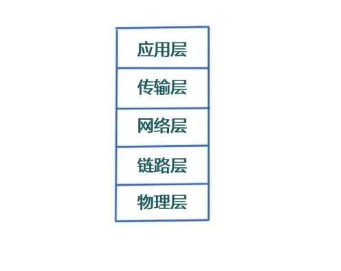
to define the communication standards between them: Protocol Stack
In the past, the OSI reference model was used to determine interconnectivity between devices, and it later evolved to use the TCP/IP Protocol Stack (as shown below). Regardless of the model, its basic function is to define the technical framework for interconnecting devices. The goal is to enable communication under the same technical model.
So what is a network?
For those who have encountered networks, you must have heard of IP routers, as they are the most widely used devices. Referring to the TCP/IP protocol stack we just saw, routers primarily operate at the network layer, with the purpose of routing and forwarding data at the network layer.
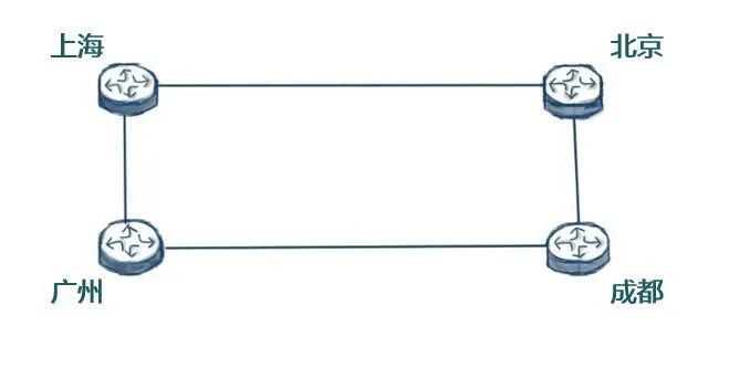
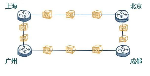
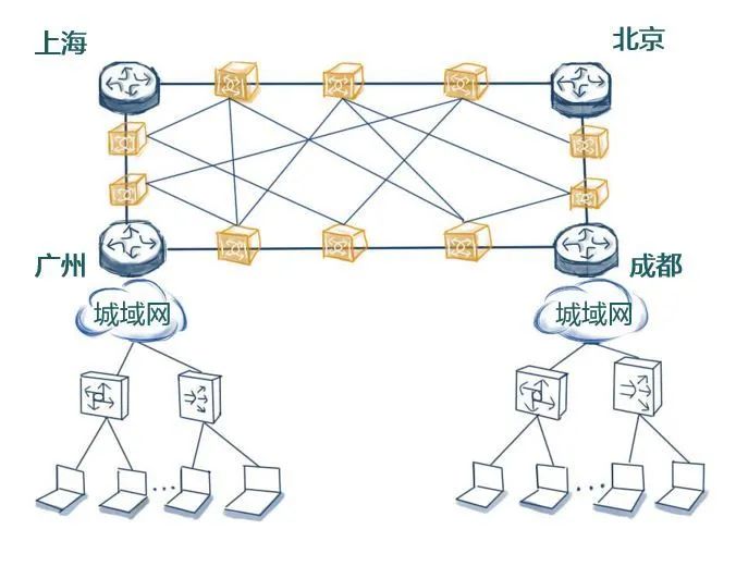
The networks formed by routers are typically called IP Networks. For example, in the image below, four major cities in China, Beijing, Chengdu, Shanghai, and Guangzhou, each have a router connected by optical fibers, forming an IP network.
If we want to form an IP network, we first need a medium for connection. Currently, the main types of connection media are: optical fibers, copper wires, or wireless (air medium). Cables made of optical fiber material are called optical cables. Copper wires include twisted pairs, such as telephone lines and networks. Wireless connections are familiar to everyone, such as wireless air interfaces and WiFi, which transmit through the air.
The interconnection between IP devices primarily uses wired methods. Generally, when signals travel through copper wires, the signal attenuation is very significant. Therefore, the transmission distance for copper wires is quite short, usually only a few kilometers.
However, we all know that the distances between the locations in the diagram are very far apart. This long distance necessitates the use of optical fibers or optical cables, but light signals also experience attenuation when transmitted through optical fibers. Although it is not as severe as with copper wires, it still cannot support very long distances.

When the signal sent from Guangzhou reaches Chengdu, it may have attenuated to a certain extent, causing the Chengdu router to receive a signal that exceeds the minimum sensitivity of the optical module, leading it to think that the light signal has been interrupted, equivalent to a line break. Therefore, the transmission distance of light signals is also limited.
Thus, we need to place some devices between the two cities. The basic function of these devices is to amplify and regenerate the light signal before sending it out again. This way, the transmission distance of the signal can be extended. If each station can cover 80 kilometers, then dozens of such relay devices would be needed between Shanghai and Beijing.
However, merely extending the transmission distance is not enough. We can imagine that if a link in the middle is interrupted, the light signals between the routers will also be interrupted. In fact, the farther the distance, the higher the risk of a link interruption, and the greater the possibility.
Therefore, we devised another solution: we find some optical cables to interconnect these relay amplification devices, forming a network of these “relay devices”.
As shown in the image below, even if a link fails (for example, it gets cut by a digger), the light signal can still take another route. Thus, the reliability of the link between the routers in Shanghai and Beijing is enhanced, providing link protection. Therefore, this network, based on optical signal wavelength multiplexing and signal amplification, which is also redundant, if isolated, we can tentatively call it Optical Transmission Network (OTN).
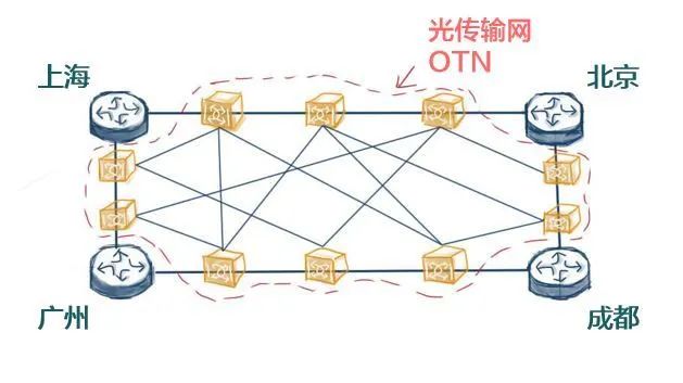
The Optical Transmission Network mainly has two functions:
First, it focuses on the wavelength multiplexing and amplification of optical signals.
Second, it ensures the reliability of the optical link. It primarily focuses on the functions of the physical layer.
As can be seen from the diagram, this network, composed of routers and transmission networks, is very important, and its reliability requirements are very high. We call it the Backbone Network. The transmission network part can be referred to as the OTN Backbone Network.
What is the purpose of carriers investing in building backbone networks?
And how do they make money?
To make money, the backbone network must access traffic to generate revenue. Where is the traffic? The traffic is with the users; where are the users? Users are everywhere!
For instance, there are many users distributed across the country. At this point, I need to connect various user terminals, such as smartphones, PCs, etc., to this network. Thus, the image below shows many PCs connected to the routers.
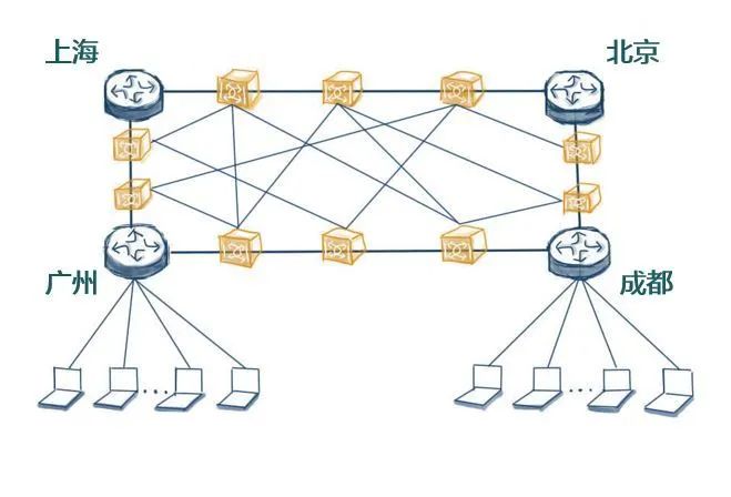
However, if the PCs in the image above connect directly to the backbone router, what problems might arise?
The most basic problem is that the number of interfaces on the router is limited, generally only a few dozen to a hundred. Backbone routers are also quite expensive. If all users connect directly to this backbone router, it is clear that the cost per port is too high, and it cannot accommodate many users. To expand capacity, the investment would be too large; this is the fundamental issue.
The second problem is that users are relatively far from the backbone router. For example, if I am not in Guangzhou but in Shenzhen, the path to connect to the Guangzhou router is relatively long, making direct connections through cables or optical fibers costly.
Therefore, based on this scenario, we must have a relatively inexpensive solution. For example, we need to add some aggregation devices between the users’ PCs and the router. This type of device can be thought of as a switch or GPON OLT, etc.
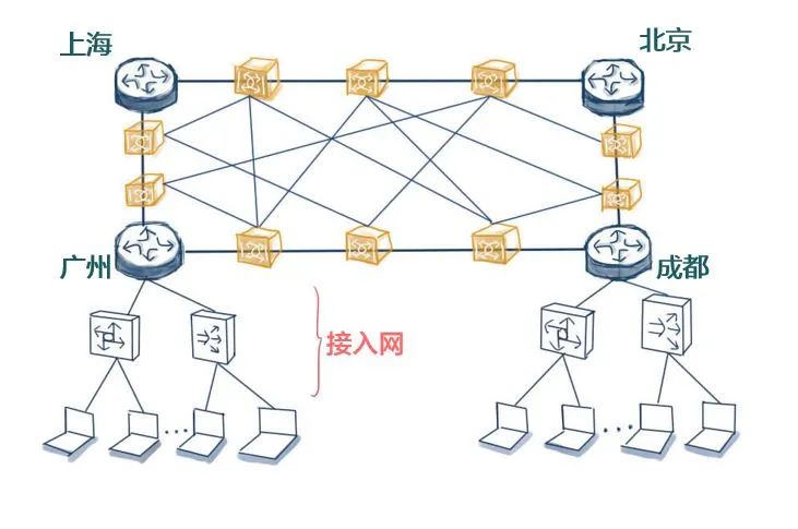
The main characteristic of these devices is that they can provide only one upstream port to connect to the backbone router and then extend inexpensive downstream ports to connect more users. This effectively aggregates multiple users into one interface, connecting to the backbone router.
At this point, the core router occupies only one port, allowing many users to connect. The cost is shared, making it relatively inexpensive. If expansion is needed in the future, we can expand the ports of switches or OLTs, as these devices are relatively cheaper. We also refer to this part of the network as the “Access Network”.
The network formed by switches is a Layer 2 forwarding network, focusing primarily on the functions of the data link layer. Layer 2 networks cannot be too large, and their scalability is limited.
Therefore, it is unlikely that a city can be covered by a single Layer 2 network. Typically, carriers will use some relatively lower-end routers to build networks to allow for flexible network expansion. Thus, the access network and the backbone network will form another network layer, the network that connects all computers in a city is called “Metropolitan Area Network”, and the network that connects several computers, allowing them to see each other’s files, is called “Local Area Network”.
Based on this architecture, let’s summarize: the relationship between the Optical Transmission Network, IP Network, and Access Network is connected to the protocol stack we discussed earlier, isn’t it?
It corresponds mainly to the lower three layers. Furthermore, these devices primarily focus on how to forward user data and do not handle user service data. We call this feature “Transparent Forwarding” or “Transparent Transmission”. Essentially, it only carries data without processing it, so some places also refer to it as Transmission Network. The large transmission network refers to the collective term for transmission, IP, and access networks.
As mentioned earlier, whether it is the access network or the backbone network, they do not handle services. So who handles the services?
Simply connecting users to the network is not enough; they ultimately need to use services. What services to access and where to process them? In fact, there must be a service processing layer at a higher level, as shown in the upper right corner of the diagram, which belongs to the service layer, mainly responsible for processing, providing, and terminating services.
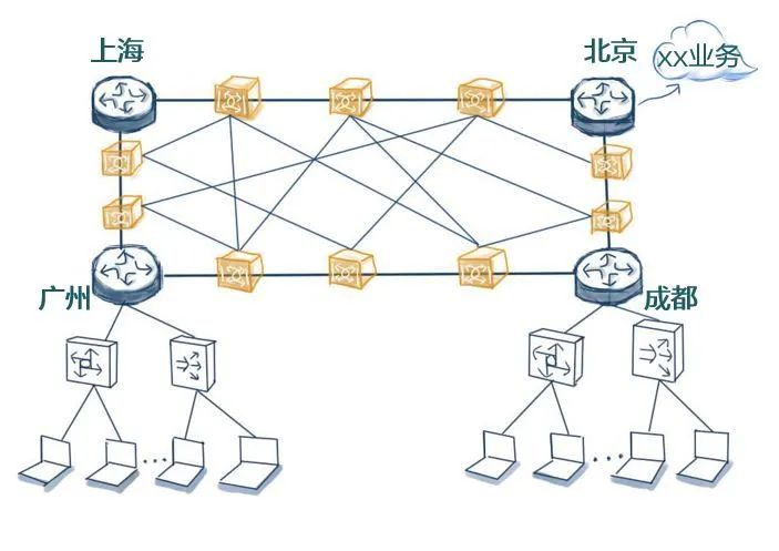
The core network’s function is mainly to provide user connectivity, manage users, and carry the services, serving as the interface to external networks, as it needs to process and distribute services across the entire network. Therefore, it is usually positioned at a higher platform level, more centrally compared to lower-layer networks, thus we refer to it asCore Network. The earliest business in our network was voice, which is telephone service.
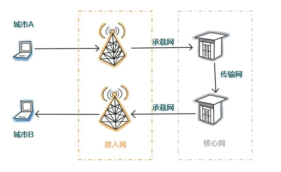
In reverse, the logical architecture of the entire communication network is:
Computer (phone) > Access Network > Transmission Network > Core Network > Transmission Network > Core Network > Access Network > Computer (phone)
Reflecting on the story of sending a package at the beginning:
Access Network = Package Distribution Center
Collecting all packages and sending them along the routes or delivering all received packages.
Transmission Network = Package Transport Routes
The purpose is to switch routes at major logistics exchange centers.
Core Network = Logistics Headquarters
Responsible for coordinating exchanges and allocations, classifying data to send to different cities and billing.
Transmission Network = Long-Distance Highways Between Shanghai and Beijing
This article provides a rough overview of the preliminary evolution of networks and services.
Transmission Network includes OTN, PTN, microwave, and SDH networking methods.
Access Network is also divided into wireless access and wired access.
Transmission Network is a broad concept, divided into front transmission, middle transmission, and return transmission.
Core Network continues to evolve with the advancement of networks.
If you want to learn more
Follow me for more sharing next time!


iOS usersplease click[Read Original]to purchase courses and learn📕
Please give a “favorite + like + see” triple click 👇