Huang Xin, Song Boyuan, Guo Xiaomin, Lin Jieqin
(Guilin University of Electronic Technology, School of Electronic Engineering and Automation, Guilin, Guangxi 541000)
Abstract: In order to utilize the traditional JTAG interface for testing and controlling a large number of specific IP testing instruments within the SOC, a universal and portable single-layer network testing method based on the traditional JTAG interface and the IEEE 1687 standard is proposed and innovatively designed. This method combines the TAP controller structure defined in the IEEE 1149.1 standard, proposing an IJTAG structure composed of an improved TAP controller and an improved IR to achieve design verification of embedded instrument testing access to the chip’s internal hardware universal interface. The testing method encompasses the SIB access mechanism and hardware structure defined in the IEEE 1687 standard, allowing the selection of built-in instructions in the IR through external test mode selection signals, enabling specific SIBs to access corresponding testing instruments. The feasibility of this testing method has been validated through simulation, thereby solving the control network problem for unified testing of various testing instruments inside the SOC. This method supports commonly used testing interface standards while proposing universal operation instructions, demonstrating high universality and portability.
Keywords: Single-layer network testing; IJTAG; IEEE standards; Test control; SOC testing; Built-in instruction selection; Design verification
Classification Number: TN711-34 Document Identification Code: A
Article Number: 1004-373X (2022) 01-0161-05
0 Introduction
As SOCs are widely used today, they have integrated a large number of functional cores, making traditional chip testing technologies unable to meet current complex testing demands[1]. To solve this development challenge, it is necessary to integrate various testing instruments (Instrument) with testing functions within the chip’s functional circuits. Therefore, when traditional JTAG can no longer meet testing requirements, it has become an urgent need to implement a control network for testing instruments within the chip[2].
The IEEE 1687 standard was proposed in 2014 to address the access and control functions of embedded semiconductor internal testing instruments. This testing standard is no longer limited to the testing functions of the standard itself but adapts to the development of integrated circuit applications by allowing personalized functional design of the testing instruments. Testers only need to establish a testing network connecting the instrument-side interface and the external interface, while utilizing PDL (Procedural Description Language) and ICL (Instrument Connectivity Language)[3] to describe the testing process, thus achieving testing access and control of on-chip testing instruments.
This paper starts from the IEEE 1687 standard and implements the testing logic and structure proposed in the standard using Verilog HDL, while defining internal instructions for SIB operations by combining the functional characteristics of the instruction register (IR) in the IEEE 1149.1 standard. It utilizes the TAP controller’s internal state machine to realize the state transitions for different testing instrument paths. This paper implements both single-layer and multi-layer testing network hardware structures, and uses ModelSim 10.1C simulation software for functional verification.
1 IEEE 1687 Standard
The IEEE 1687 standard mainly addresses the access to a large number of specific functional testing instruments within the chip by the following points:
1) By establishing an instrument connectivity language (ICL) that describes the instruments and the access paths between instruments;
2) By establishing a procedural description language (PDL) for accessing specific functional testing instruments on the chip;
3) By implementing specific on-chip instrument testing controllers and testing interfaces[3].
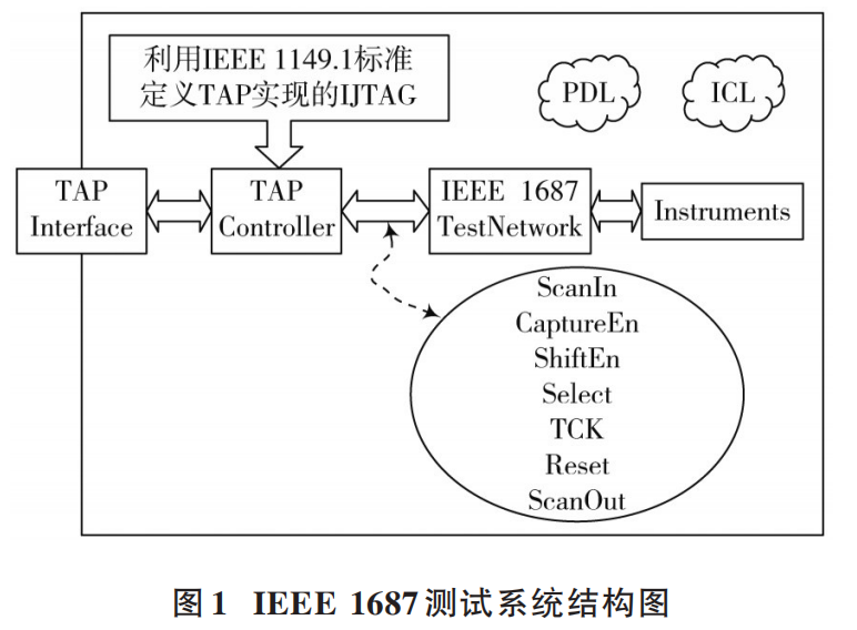
As shown in Figure 1, this figure describes a complete IEEE 1687 testing network within a chip, where the external testing interface utilizes a standard JTAG interface design, and the backend must select a matching TAP controller, which is derived from the definition of the IEEE 1149.1 standard. In this diagram, it can be defined as Internal JTAG (IJTAG), which is the controller that truly controls the testing process inside the chip; at the same time, the controller controls the testing operations and reads the corresponding test data based on internal state transitions using output enable signals to control the testing network.
2 Overall System Design and Improvements
2.1 Overall System Design
As shown in Figure 2, this paper proposes an overall testing system implementation scheme utilizing the TAP controller of the IEEE 1149.1 standard combined with the testing definitions of the IEEE 1687 standard. Here, the PC (which can be replaced by other microcontrollers) acts as the upper computer in the design, connecting to the JTAG interface of the chip under test through the testing bus. The JTAG interface connects to the internal IEEE 1687 testing network (SIB testing network), thus implementing the overall testing process.
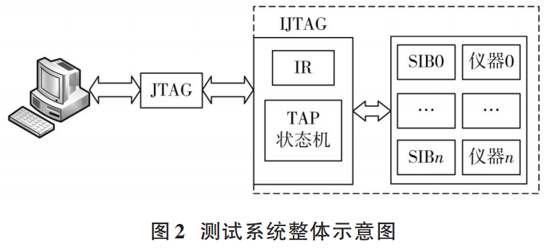
Connecting the TAP (Test Access Port) for external testing to the internal testing becomes the focus of the entire design. Therefore, in this design, the IJTAG (Internal JTAG) in the IEEE 1687 standard is improved and defined, where the TAP state machine controlling testing state transitions is combined with the IR (Instruction Register) to form two parts that control testing state transitions and output instructions, constituting the IJTAG part of this design. Practical innovations have been made to the built-in TAP (eTAP) described in the standard, proposing this structure.
2.2 IJTAG Improved Design
2.2.1 SIB Structure Design
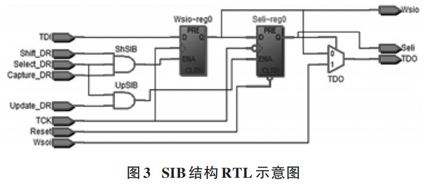
Figure 3 illustrates the hardware structure of the proposed SIB in this design, consisting of a shift register and an update register. It performs switch-like operations based on the instructions issued by the TAP controller to determine whether the connected testing instruments are included in the testing link[4]. TDI (Test Data Input) is controlled by the shift enable signal to shift data into the Shift register bit by bit, which will latch this signal until the next shift arrives. Thus, data can be shifted into the corresponding positions in the SIB, so before inputting TDI, 0/1 instructions (representing switches) should be shifted into each SIB bit by bit, and the UpdateDR (Update Enable) signal enables all SIBs to update the Seli (Testing Instrument Enable) signals according to the instruction state.
2.2.2 IR Structure Improvement Design
The single-layer testing network structure composed of SIB, where each SIB corresponds to two instructions (0/1) representing the opening and closing of SIBs, thus for this network structure, an instruction set as shown in Table 1 is defined in the IR.
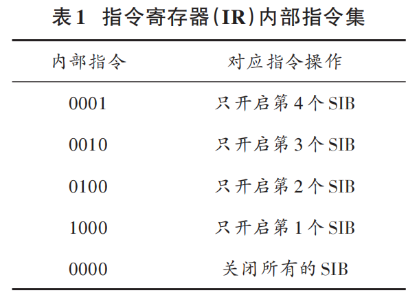
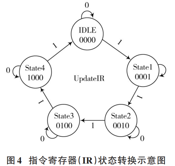
As shown in Table 1, five instructions are set to represent the testing states of five SIBs, namely fully open and the opening and closing of individual SIBs. By this method, the states of various SIBs can control the selection of connected testing instruments to enter the testing link, facilitating the subsequent TDI input for the selected testing instrument to perform testing operations. The corresponding instructions are pre-set in the IR, but when completing the current testing instruction or requiring other instructions, the state machine for instruction conversion needs to be set in the IR according to this requirement.
As shown in Figure 4, UpdateIR serves as a driver for state transitions output by the TAP state machine. The states given in the table are changed through the triggering of UpdateIR, and the triggering occurs on the falling edge of the test clock, thus realizing the operational flow from external testing instructions to the internal TAP state machine and to the IR.
3 Improvement of IEEE 1687 TAP Controller
Based on the content described in the previous section, the state transitions of various parts within the IJTAG and the operations of capturing, shifting, and updating within the SIB testing network all require the enabling signals outputted by the state machine within the TAP controller for control. Therefore, the design of the TAP controller is crucial for achieving the overall design[5].
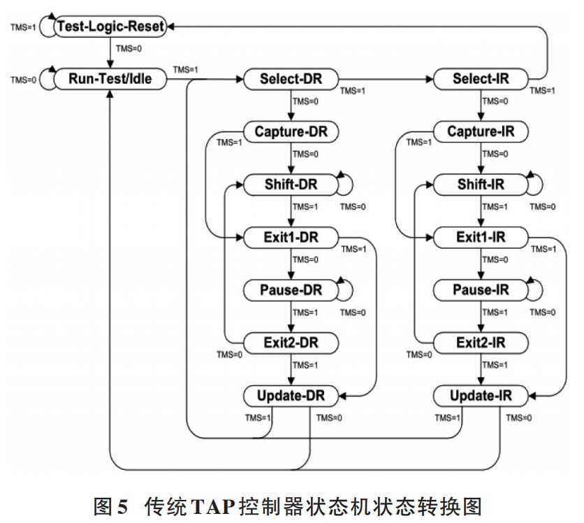
According to the definition in the IEEE 1687 standard, the TAP state machine from the IEEE 1149.1 standard is directly adopted. Figure 5 shows the internal transition diagram of the TAP state machine, which lists a total of 16 states. This state transition diagram illustrates the transition methods for triggering various states of the TAP function in traditional TAP state machines. In this design, the transition of this state machine is inherited, and different enabling signals are triggered dynamically through different states to control the states and instructions of each SIB as well as the test data shifting into[6].
According to the requirements of this design, operations on the SIB testing network need to utilize Select, Capture, Shift, and Update. Unlike the serial shifting operations in traditional boundary scan testing, the IEEE 1687 testing network first requires state control operations on the SIB. Therefore, the states of the state machine need to be precisely controlled according to timing, and based on the IR part added in this design, the IR operation state transition commands also need to utilize similar ideas for state machine transitions as in TAP. By controlling the TDI and IR output (as shown in Figure 4) through a data selector, the SelectIR (Select IR) signal achieves the switching of instructions in TDI and IR, while ShiftIR (Shift IR) controls the IR instructions selected within the IR to be shifted out from the instruction register. UpdateIR (Update IR) controls the internal instruction state transitions of the IR, selecting the corresponding test instructions based on the input instructions.
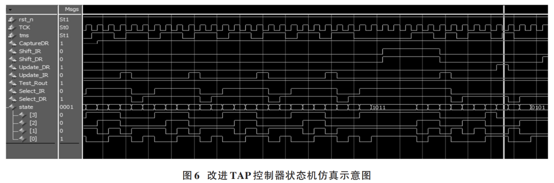
Based on the design concepts described above, the improved TAP controller generates control enabling signals for the IR and SIB testing network, as shown in Figure 6. The verification in this simulation state demonstrates the process of enabling the fourth SIB through four state transitions. By updating each state, the TMS signal serves as an external testing mode selection instruction, issuing the serial instruction “011011”. The TAP controller’s internal state machine transitions to the UpdateIR state. UpdateIR first sets to 1, and the IR internal state machine transitions to the “State1” state. According to the design of the internal state machine’s state transitions, it continues to execute the three “011011” instructions, and the IR internal state machine undergoes three similar state transitions, reaching the “State4” state, which is the target state for this instruction. Thus, the next operation requires shifting the corresponding state instruction out from the instruction register, executing the “01100000110” instruction. Compared to the previous state transitions, this operation adds five clock cycles, of which four cycles are for the instruction register to perform four shifts to shift the corresponding instruction into the SIB single-layer network, completing the IR operation. Thus, the next step (as indicated by the yellow line in the simulation diagram) requires setting UpdateDR to 1, completing the state update of the SIB testing network.
Through simulation experiments, the improved TAP controller has been verified to effectively perform instruction state transitions and instruction output operations for the IR, proving the feasibility of the overall IJTAG design to control the SIB testing network using external test mode instructions.
4 Validation of Single-Layer Testing Network Design
As shown in Figure 7, a four-bit SIB single-layer testing network is used as the network validation carrier, utilizing four multi-bit test data registers (i.e., TDR) as the caching objects for the instruments connecting to the testing network.
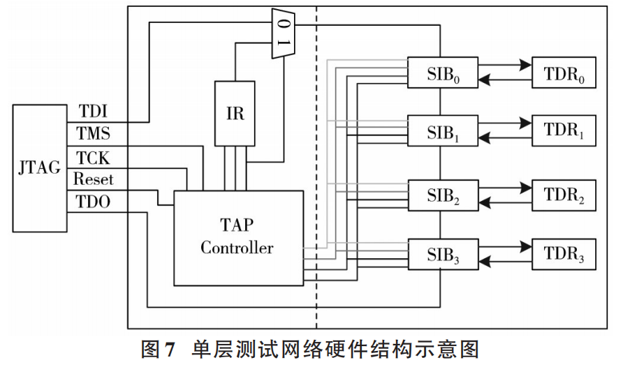
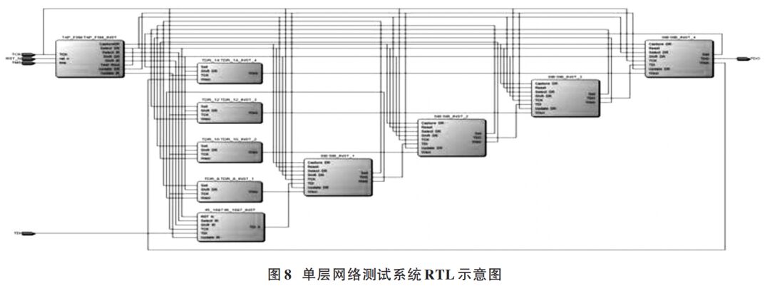
According to the previously discussed hardware structure, Verilog HDL is utilized to implement RTL-level code for the hardware structure. Through modular programming, Quartus 13.0 is used to synthesize the project, yielding the RTL schematic of the hardware system based on the single-layer SIB testing network, as shown in Figure 8.
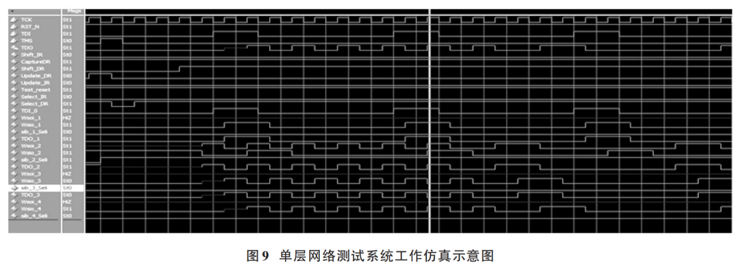
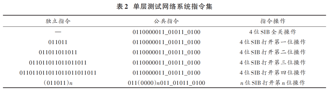
Based on the hardware structure design, ModelSim 10.1C simulation software is required to conduct timing and logical simulations on the involved projects to validate the correctness and accuracy of the overall design. According to the instruction set defined in Table 1, a Testbench is written to provide the necessary excitation inputs for the system. The outputs generated are observed using simulation software, as shown in Figure 9. The simulation input TMS (Test Mode Selection) signal issues the instruction “011011_011011” to complete the corresponding state instruction in the IR (i.e., the open SIB2 instruction). After this step, the instruction “0110000011_01011_0100” is issued. This instruction consists of three parts: the first part performs shifting operations on the determined state instruction register, latching all instructions into the corresponding SIB positions; the second part updates the instructions, executing update operations on the SIB’s update register through the TAP state machine’s internal state transitions, opening and closing the relevant SIB; the third part is the shifting instruction, which, after the SIB’s update state, shifts the values from the TDR (Test Data Register) out and inputs the values from TDI (Test Data Input), initiating the testing process. TDO (Test Data Output) outputs the value “1010101010” from the TDR and continues to output the values from TDI, demonstrating the feasibility of the overall testing system. Based on the simulation operations, the instructions derived can be summarized in Table 2, with instructions divided into independent and common parts, providing significant regularity and readability for subsequent operations on the upper computer.
This paper proposes a single-layer network testing method based on the IEEE 1687 and IEEE 1149.1 standards, which combines the structure of the TAP controller defined in the IEEE 1149.1 standard to form an IJTAG structure composed of an improved TAP controller and an improved IR, achieving design verification for embedded instrument testing access to the chip’s internal hardware universal interface. This testing method encompasses the SIB access mechanism and hardware structure defined in the IEEE 1687 standard, allowing selection of built-in instructions in the IR through external test mode selection signals, enabling specific SIBs to access corresponding testing instruments.
This paper also utilizes mainstream EDA software such as Quartus and ModelSim for synthesis and simulation verification of various hardware structures, summarizing and verifying the test operation access instructions, proving that this testing method has high feasibility and universality.
References
[1] Ma Xinyu, Xu Hanyang, Wang Jian. General Testing Method for SOC Embedded Digital IP Cores [J]. Microelectronics and Computer, 2019, 36(2): 26-30.
[2] Zadegan F G, Nikolov D, Larsson E. A self-reconfiguring IEEE 1687 network for fault monitoring [C]// 2016 21th IEEE European Test Symposium (ETS). Amsterdam, Netherlands: IEEE, 2016: 1-6.
[3] IEEE. IEEE standard for access and control of instrumentation embedded within a semiconductor device: IEEE Std 1687-2014 [S]. New York, USA: IEEE, 2014.
[4] Liu Yang, Yan Xuelong. Design of Variable Scan Chain Based on IEEE P1687 [J]. Computer Measurement and Control, 2012, 20(9): 2357-2359.
[5] Xu Zhiqiang. A Design and Implementation of SOC Testability Based on IEEE 1149.1 and IEEE 1500 [D]. Xi’an: Xi’an University of Electronic Science and Technology, 2019.
[6] Yan Xuelong, Jia Yintao. Design and Implementation of Boundary Scan Test Systems [J]. Foreign Electronic Measurement Technology, 2016, 35(6): 82-85.
[7] Zadegan F G, Nikolov D, Larsson E, et al. On-chip fault monitoring using self-reconfiguring IEEE 1687 networks [J]. IEEE Transactions on Computers, 2018, 67(2): 237-251.
[8] Jutman A, Shibin K, Devadze S. Reliable health monitoring and fault management in infrastructure based on embedded instrumentation and IEEE 1687 [C]// 2016 IEEE AUTOTESTCON. Anaheim, CA, USA: IEEE, 2016: 1-10.
[9] Jutman A, Devadze S, Shibin K. Effective scalable IEEE 1687 instrumentation network for fault management [J]. IEEE Design & Test, 2013, 30(5): 26-35.
[10] Wu Libin. Design and Verification of Testability for Integrated Circuits [J]. Wireless Interconnection Technology, 2016(11): 113-114.
[11] Kumar S K, Satheesh N, Mahapatra A, et al. Physical unclonable functions for on-chip instrumentation: enhancing the security of the internal joint test action group network [J]. IEEE Consumer Electronics Magazine, 2019, 8(4): 62-66.
[12] Baranowski R, Kochte M A, Wunderlich H J. Reconfigurable scan networks: modeling, verification, and optimal pattern generation [J]. ACM Transactions on Design Automation of Electronic Systems (TODAES), 2015, 20(2): 1-27.
[13] Baranowski R, Kochte M A, Wunderlich H J. Access port protection for reconfigurable scan networks [J]. Journal of Electronic Testing, 2014, 30(6): 711-723.
Author Information:
Huang Xin (1978—), male, from Ying Shan, Hubei, Master, Senior Experimentalist, research direction in computer-aided testing.
Song Boyuan (1995—), male, from Chengwu, Shandong, Master’s student, research direction in testability design.
Guo Xiaomin (1995—), female, Master’s student, research direction in medical image processing.
Lin Jieqin (1997—), female, Master’s student, research direction in testability design.
-End-
Click the link below to view historical articles
Good papers are “revised”!
CNKI’s continuous price increases are suspected of monopoly; how should academia and business balance?
Table of Contents for Modern Electronic Technology 2019 Issue 12
Which universities published the most SCI papers and authorized patents in 2017?
Modern Electronic Technology is included in the Overview of Chinese Core Journals
Academician of the Chinese Academy of Sciences: The dominance of SCI in papers stifles scientific creativity
How to write a “Nature” article overnight, listen to what the academicians say!