Click on the blue text above to follow C-ASAM
In 2022, the ASAM Evolving Landscapes of Collaborative Testing for ADAS & AD White Paper was officially released. The preceding tweets provided readers with an overview of SIL and HIL testing in the new testing strategy blueprint for ADAS & AD, this article will detail Fault Injection Testing in the MIL environment.
Introduction to MIL Environment
MIL (Model in the Loop) testing is used to test individual or integrated modules in a model-based development environment, simulating the model and validating whether it meets the design requirements through a series of test cases.
Regarding MIL testing under the new testing strategy blueprint, it is mentioned in the article “Collaborative Testing White Paper for Autonomous Driving | In-depth Interpretation of the New Testing Strategy Blueprint for Model in the Loop Testing”, readers can review it.
Detailed Explanation of Fault Injection Testing
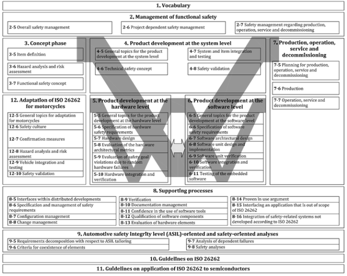
Fault Injection Testing (FIT) is a commonly used software testing method. It is an important part of the testing phase on the right side of the ISO 26262 process model, distributed across seven development phases: software unit verification, software integration verification, software validation, hardware testing verification, software-hardware integration verification, system integration and testing validation, and vehicle integration and testing validation.
ISO 26262 Overall Framework
Fault injection testing is used to simulate various fault scenarios that may occur in software systems. In this testing method, engineers intentionally introduce various faults into the software system to detect and assess the system’s reliability and stability, thereby improving the quality of the software system.
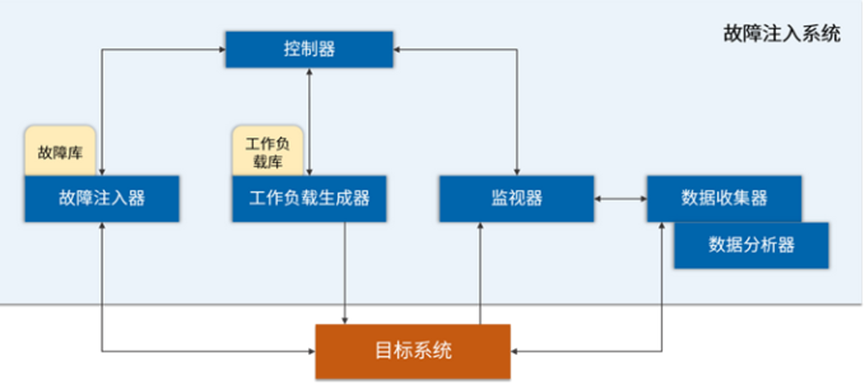
Fault injection techniques were initially applied mainly in reliability testing within the aerospace industry and have gradually gained widespread application in the field of computer science. Currently, fault injection technology has become a very important part of software testing, widely used in flight control, train signaling, and industrial automation.
Example of a fault injection system in a certain field
In autonomous driving systems, fault injection testing mainly includes two purposes: first, to check whether the functionality designed to operate in a fault-tolerant manner actually maintains fault tolerance; second, to analyze the behavior of non-fault-tolerant functionalities when they fail due to specific faults.
Fault Injection Testing in MIL Environment
For requirement-based MIL testing, model-level fault injection testing aims to discover defects in functional models. This differs from subsequent testing activities, such as hardware-in-the-loop testing, which occurs at a stage where the system under test is assumed to be error-free.
MIL testing occurs soon after model development or even during the model development phase. Therefore, compared to hardware-in-the-loop testing, the feedback cycle of fault injection testing is relatively short, and the cost of error correction is lower. Additionally, fault injection testing is very effective and highly automated in MIL environments, allowing hundreds of fault tests on the system per minute, resulting in fully reproducible results.
Of course, fault injection testing in MIL environments also has limitations. For example, MIL testing cannot simulate faults that do not belong to the environmental model components, such as sensor faults. In these cases, only the expected impact of the fault on the model can be simulated, which is sufficient for test-driven development but not for proper system confirmation. Similarly, it is also challenging to test hardware robustness in MIL environments, which involves applying physical stress to the device.
The following test cases will describe how to apply fault injection testing in a MIL testing environment and in what situations and aspects it can supplement classical fault injection testing activities conducted at the hardware level.
As mentioned earlier, MIL fault injection testing is very suitable for checking and assessing the behavior of functional models under fault conditions, mainly checking the response of the functional model to faults. Measures such as fallback modes or fault-tolerant controls are typically implemented in software and are already part of the code-derived or generated functional model. In these cases, what is nominally referred to as a “fault” is merely another valid input to the model under test.
Another scenario involves faults occurring within the model being tested. Whether external or internal faults, they can be simulated and evaluated using appropriate MIL testing tools.
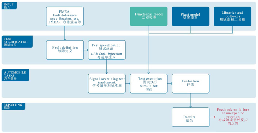
General Fault Injection MIL Testing Process
Typically, the basis for fault injection testing is a test document that archives and specifies the different types of faults and their potential, required, and prohibited impacts on the functional system. From these documents, test engineers derive semi-formal definitions of specific faults they want to test in the system. These may be external or internal faults, or even a combination of both.
Based on these definitions, specific testing specifications can be derived, usually following a general pattern:
(1) Initialize the system and drive it to a certain state via regular stimulation;
(2) Inject a fault to the environment model or to the stimulation of the model under test or into the model under test;
(3) Continue stimulation and capture the system’s behavior under the fault;
In addition to simulation, the document should also include the expected response to faults in terms of anticipated internal and output signals. Fault injection testing is typically applied in a closed-loop manner, where the input ports of the system under test are stimulated by the environmental model, while the environmental model consumes its output in return. In most cases, neither the environmental model nor the model under test provide any fault injection mechanisms. Therefore, testing tools need to identify the variables/signals to which faults should be injected and override them with specified fault values.
During the simulation, it is essential to capture all relevant data. This data particularly includes (regular) stimulation, all variables/signals with which a fault is injected, and all output signals and internal signals. Through these signals, the behavior of the system when a fault occurs can be understood.
For requirement-based MIL testing, the recorded signals can be automatically evaluated in the post-processing step against the expected signals, generating easily readable test reports.
Example of Adaptive Cruise Control
Taking Adaptive Cruise Control (ACC) as an example, consider testing the system against an environmental model that provides the necessary input for the tested adaptive cruise control model, including simulated sensor values for the distance to the vehicle in front.
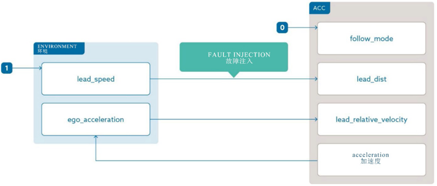
Simplified ACC Model Example
The fault tolerance specification states that a sudden fault in the distance sensor should not lead to hard (potentially dangerous) deceleration of the ACC.
In this example, faults are injected into the closed-loop simulation of the model under test. Based on the electrical characteristics of the sensor, the test engineer determines two different logical signal values that may be provided to the system in the event of a sensor fault: 0 and NaN.
The following is a parameterized test specification, where the lead car can accelerate to 40 km/h within 8 seconds, after which it remains constant, during which the ACC is enabled. The ego car follows the lead car at a distance of 40 meters. Two seconds after reaching the final speed of 40 km/h, the fault is injected by immediately overriding the distance value with a parameter.
The simulation will continue for 5 seconds. Throughout the process, at least the following signals are captured: speed of the lead car, speed of the ego car, distance to the lead car, and acceleration. It is important to note that some of these signals are internal signals of the environment.
Two test cases are generated for implementation, with parameter values of 0 and NaN, and executed automatically. To evaluate the tests, the acceleration output of the adaptive cruise control model is scanned to determine values below the legal threshold. Subsequently, a fault injection test report can be generated and sent back to the model engineer or archived based on the research findings.
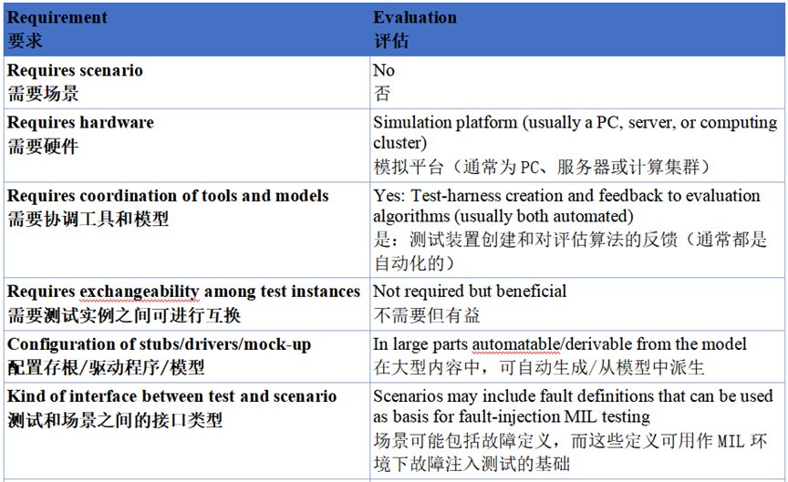
The table below lists some requirements and features of the shown example for quick comparison with other user journeys according to general standards.
Requirements for Test Specifications
The above is an overview of the fault injection test cases in the MIL environment of the ADAS & AD new testing strategy blueprint, in the next article we will continue to interpret other test cases. The goal of this series of interpretations is to jointly promote the orderly development of autonomous driving science, so stay tuned for more exciting content!
To obtain the original white paper document, please follow the “CASAM Standard Organization” public account and enter the keyword “Test2022” to get the download link from the official website.
C-ASAM adheres to the philosophy and mission of the ASAM standard association and will continue to work to build a mutually supportive industry platform for members in China, organize technical exchanges and sharing among members, and jointly promote the development of global automotive autonomous driving simulation technology. Welcome to follow the C-ASAM Standard Organization public account!
C-ASAM Working Group Contact: Wei Wenyuan
Mobile: 15022601236
Email: [email protected]
Collaborative Testing White Paper for Autonomous Driving | Software and Hardware-in-the-Loop Testing under New Testing Strategy Blueprint (SIL&HIL)
Collaborative Testing White Paper for Autonomous Driving | In-depth Interpretation of the New Testing Strategy Blueprint for Model in the Loop Testing
Presentation Review | Tongji University and CATARC Fourth (2023) ASAM China Regional Conference Keynote Speech Overview
Presentation Review | Pateo Automotive and 51WORLD Fourth (2023) ASAM China Regional Conference Keynote Speech Overview