Using an AVR64DD32, a temperature sensor, and a few lines of PWM control code, a stable temperature control system can be built. This project demonstrates the complete implementation process from temperature acquisition, closed-loop control to UI display, providing an in-depth exploration of the capabilities of an 8-bit MCU.

Project Overview
This design primarily uses the AVR64DD32 Curiosity Nano evaluation board and the Hard Core Classroom functional expansion board. The AVR64DD32 microcontroller mainly implements information acquisition, user UI display, and logic control functions, while the Hard Core Classroom functional expansion board implements physical functions such as buttons, rotary control, indicator lights, and LCD display.
This project design mainly accomplishes the task of implementing an automatic temperature control system and includes temperature curve display functions. The IOBV3 functional expansion board has a heating resistor and senses temperature changes on the board through a temperature sensor, measuring temperature and displaying it on the LCD screen. The target temperature can be set using buttons, and the program controls the heating power to maintain the temperature as close to the target as possible. If the temperature deviates from the set temperature by ±3°C, the indicator light turns red.


Hardware Composition and Scheme
The main control of this project is the new AVR microcontroller AVR64DD32 Curiosity Nano development board produced by Microchip, which features a highly capable 8-bit microcontroller with a rich set of peripheral resources.
Core Microcontroller: AVR64DD32: Multi-Voltage I/O
https://www.eetree.cn/doc/detail/2576
The AVR DD series is the latest member of Microchip’s AVR microcontroller product line, featuring a flexible internal structure and powerful performance, with a rich set of peripherals and storage resources. This series employs the latest non-core-dependent peripherals, enabling safe bidirectional communication across various voltage inputs and outputs with very low power consumption. The event system, configurable logic (CCL), and intelligent analog peripherals, such as a 12-bit ADC and zero-cross detection, make the AVR DD series highly suitable for sensing, IoT endpoint nodes, and other applications requiring signal conditioning and level shifting. It operates at speeds up to 24 MHz and has 64 KB of flash memory, 8 KB of SRAM, and 256B of EEPROM.
The AVR64DD32 product supports four multi-voltage I/O channels, allowing bidirectional communication with external devices operating at voltages above or below that of the MCU itself. The MVIO system makes the AVR® DD a perfect device for control on circuit boards, sensor applications, IoT endpoint nodes, and other size-constrained applications, as well as sensor fusion in larger systems.
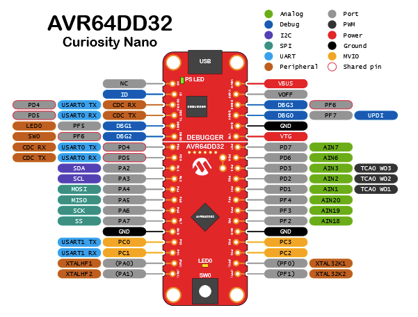
The relevant functions and pin peripherals are shown in the figure below:
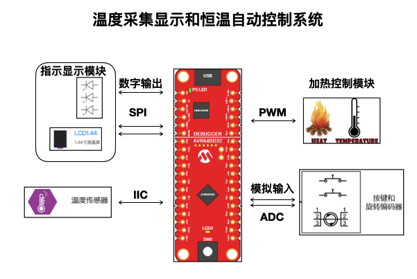
This design mainly implements temperature acquisition display and an automatic temperature control system, consisting of the following internal components: temperature acquisition module, indicator display module, heating control module, and button/knob operation recognition module:
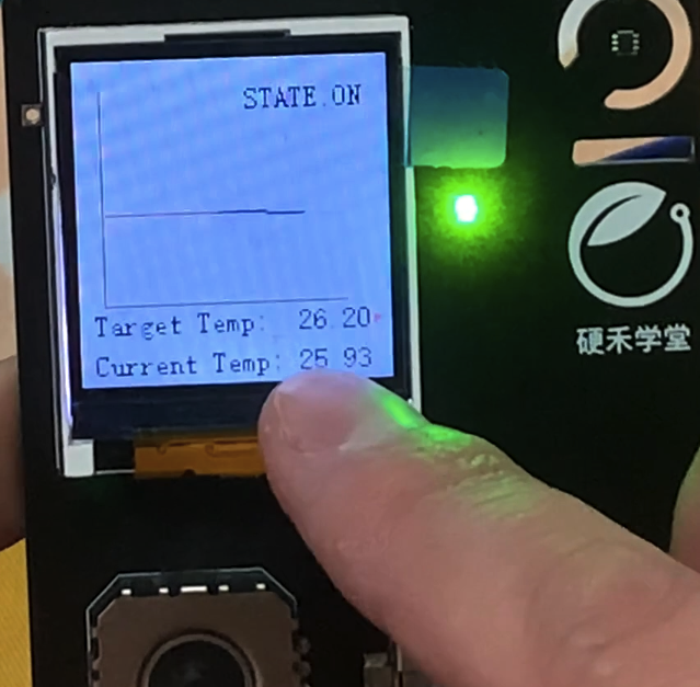
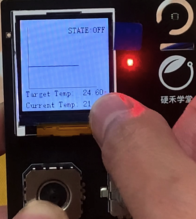
- Indicator Display Module: Displays real-time temperature curves, shows the on/off state of temperature control, and indicates temperature difference status. If the target temperature differs from the current temperature by more than 3 degrees, a red light is displayed; if the difference is less than 3 degrees, a green light is displayed.
- Temperature Acquisition Module: Uses the NST112 temperature acquisition sensor to collect temperature via IIC communication.
- Heating Control Module: Uses a MOSFET gate to drive the heating resistor for temperature control, with PWM duty cycle controlling heating intensity.
- Button and Knob Operation Recognition Module: Uses the ADC function of the AVR64DD32 to perform analog-to-digital conversion and recognition of the voltages generated by different button and knob operations.
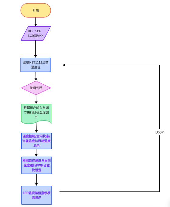
The design flowchart is shown in the figure: First, initialize IIC, SPI, button control ADC, and LCD, then continuously read the current temperature value in the main loop, adjust the target temperature based on user input and adjustments, and update the display and status indicators.


Related Modules and Function Implementation
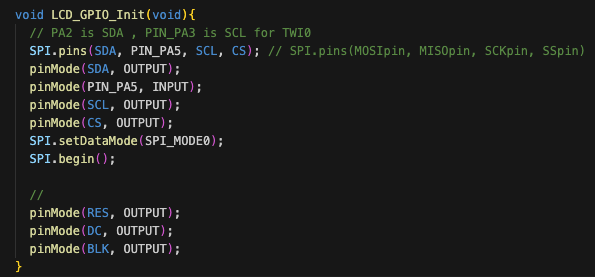
Display module code implementation, based on the LCD manufacturer’s source code, creating the LCD_init.h file, implementing SPI functionality through PA4, PA5, PA6, PA7, and adding RES, DC, BLK interfaces, modified as follows:
#include "Arduino.h"
#include "lcd_font.h"
#include
#define SDA PIN_PA4
#define SCL PIN_PA6
#define CS PIN_PA7
#define RES PIN_PF2
#define DC PIN_PF3
#define BLK PIN_PF4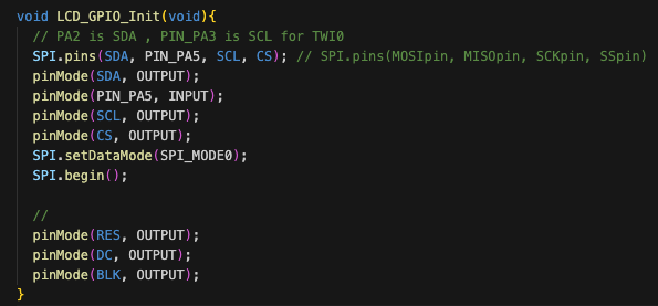
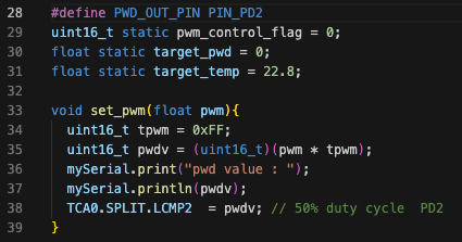
 Temperature control uses PWM duty cycle to adjust heating intensity, as shown in the following code initializing the TCA0 peripheral PWM function, using PD2 as the PWM output interface:
Configure TCA0.SPLIT.CMP2 to adjust the duty cycle:
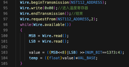
 Temperature reading model, using IIC interface to read real-time temperature: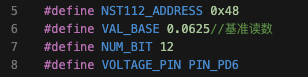
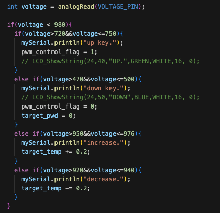
 Button and knob reading, using ADC:
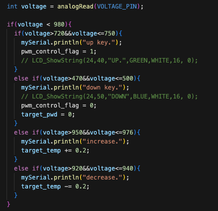
 PWM control section based on temperature difference: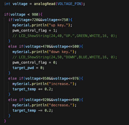

Effect Demonstration
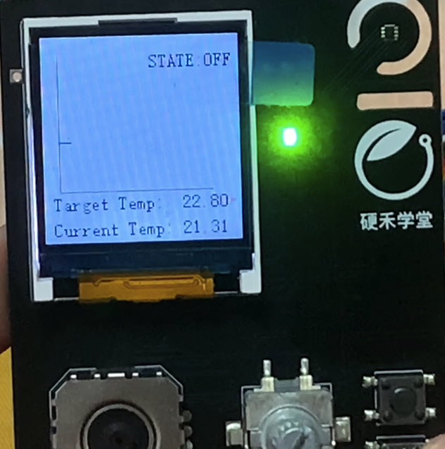
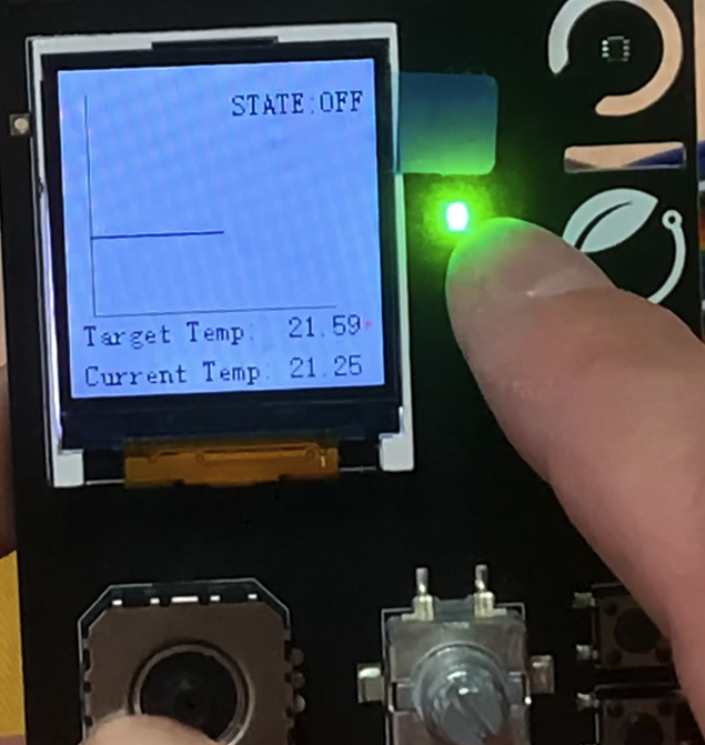
In idle state, STATE: OFF, the current temperature control mode is off:
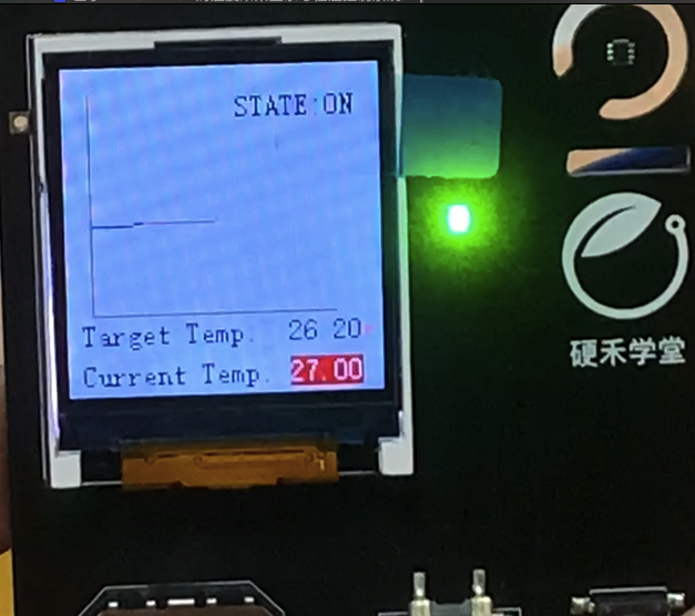
When the temperature control mode is on, it performs constant temperature control, with the temperature curve slightly fluctuating around the target temperature:
When the temperature control mode is on, if the temperature difference is less than 3 degrees, the green light is on:
When the temperature control mode is on, if the temperature difference is greater than 3 degrees, the red light is on:


Insights and Summary
1. The experience of using hardware development tools is very important: This time, the Arduino IDE was used for the development and application of the AVR64DD32 microcontroller, facilitating quick development and verification, simplifying the development process, and reducing the chances of errors. At the same time, the official IDE editor provided a graphical configuration interface through MCC, which will become increasingly popular, further reducing the workload of engineers and allowing them to focus on functional development, making it more user-friendly.
2. Technical communication and mutual assistance are key to learning and progress. The completion of this activity relied on the help and guidance of friends in the technical exchange group. Through communication, one can broaden their horizons, avoid detours, and save time. I hope such technical activities can continue to be held to promote more technical exchanges.
3. Trying new technologies and products hones the ability to learn quickly. This experience with the AVR64DD32 8-bit microcontroller trained the ability to quickly master a new device. Although the products differ, familiar development processes and tools allow for quick onboarding, and the activity provided a platform for everyone to try new technologies.

Click to read the original text for more information