I²C (Inter-Integrated Circuit, pronounced “I-squared-C”) is a very elegant and widely used synchronous, serial, half-duplex communication protocol. Its core appeal lies in the fact that it can connect multiple devices using only two wires while sacrificing communication efficiency for individual devices.
The bus data topology and device connections are shown in the following diagram: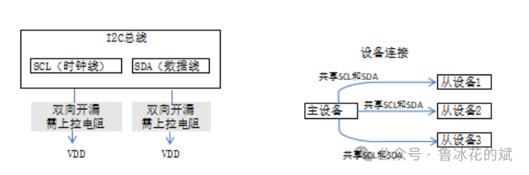
Taking the example of the master device reading data from a slave device, the communication process is as follows: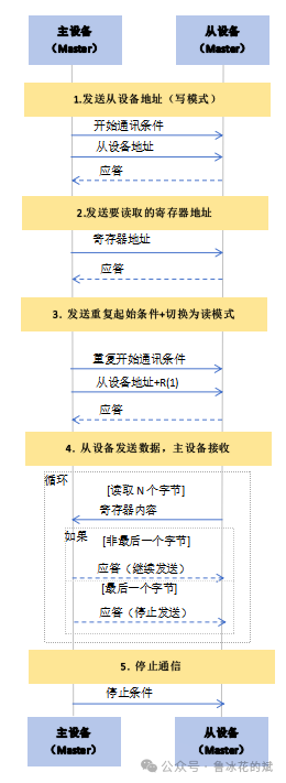
Detailed explanation is as follows:
Step 1: Send Start Condition + Slave Device Address (Write Mode)
The master device pulls the SDA line low while SCL is high, generating a START condition, notifying all devices on the bus to start communication.
The master device first sends a7-bit (or 10-bit) slave device address. This informs the devices on the bus who the master intends to communicate with next.
Next, the master device sends the8th bit – Read/Write Control Bit. This tells the addressed slave device that the master will send a command to it next; this bit must be set to0, indicatingWrite Mode.
Once the addressed slave device recognizes its address, it pulls the SDA line low during the 9th clock pulse as anAcknowledge (ACK).
Step 2: Send Register Address (or Command)
The master device sends one or more bytes of data. This is usually the
address of the internal register of the slave device, informing the slave device from where to start reading data.
After sending each byte, the slave device must respond with anACK, indicating it is ready.
Step 3: Send Repeated Start Condition + Slave Device Address (Read Mode)
The master device generates anotherStart Condition (Sr). This start condition is identical to the initial start condition but occurs during an ongoing communication, hence it is called aRepeated Start Condition.
The master device sends the same7-bit slave device address.
However, this time theRead/Write Control Bit is set to1, indicatingRead Mode. This switches the read/write mode.
The slave device recognizes the address again and responds with anACK.
Step 4: Slave Device Sends Data, Master Device Receives and Acknowledges
Direction Switch: Now theslave device starts controlling the SDA line, while themaster device is responsible for generating the SCL clock and reading data from the SDA line.
The slave device begins to send data byte by byte.
After sending each byte, themaster device must respond with a signal during the 9th clock pulse:
Acknowledge: Indicates “Received, please continue sending the next byte.”
No Acknowledge (NACK): Indicates “Received, but this is the last byte, please stop sending.”
Step 5: Send Stop Condition
The master device pulls the SDA line high while SCL is high, generating a Stop Condition (P).
The bus is released, and communication ends.
Common application scenarios for I2C communication mode are as follows:
Sensor Data Acquisition (Most Common Use)
This is the most classic application scenario for I2C. The master MCU needs to read data from multiple sensors, which can be connected to the same I2C bus.
User Interface and Display
OLED/LCD Screens: Many small-sized OLED display modules (such as SSD1306, SH1106 driver chips) use I2C interfaces, requiring only 4 wires (VCC, GND, SDA, SCL) to drive.
Touch Sensors: Capacitive touch controllers commonly use I2C to report the coordinates of touch points to the host.
Smart LED Drivers: For example, PCA9685 can be used to control multiple servos or RGB LED lights.
System Management and Chip Configuration
In more complex systems, I2C is often used to manage hardware and configure the operational states of other chips.
IO Port Expansion: When the GPIO pins of the MCU are insufficient, I2C interface IO expansion chips (such as PCA9538, MCP23008) can be used to increase input and output ports, controlled via I2C commands.
Thought: Is a USB hub using this kind of solution?
Real-Time Clock: RTC chips (such as DS3231, PCF8563) provide accurate year, month, day, hour, minute, and second time, usually set and read via I2C.
EEPROM Memory: Stores small amounts of non-volatile data, such as product serial numbers, device configuration parameters, user settings, etc. Chips like AT24C02, AT24C64.
Power Management: In smartphones and embedded systems, power management chips (PMIC) communicate with the main CPU via the I2C bus to dynamically configure the power supply voltage and switches for different circuit modules to achieve energy savings.
Audio Codec: Configures audio chip parameters such as volume, input/output channels, equalizer, etc.
Digital Circuits and Bridging
ADC/DAC Converters: Many high-precision Analog-to-Digital Converters (ADC) and Digital-to-Analog Converters (DAC) use I2C interfaces, facilitating the main control chip to read or output analog signals.
Bridge Chips: I2C can be used to configure chips for other bus interfaces, such as configuring USB bridge chips, configuring serial port expansion chips, etc.