
In practical control projects centered around PLCs, the vast majority of cases rely on the collaboration of touch screens or host computers. This is because we use PLCs for control, mainly to handle some analog quantities, which are the values we need to monitor, such as pressure, temperature, and flow on the equipment. These detected values are then used to control electric valves, fans, pumps, etc., based on certain conditions. However, we cannot see these values directly from the PLC; to view them, we need to use a touch screen or an industrial computer (which is essentially a computer).
First, it is important to clarify that this article only describes the general working principle and process of touch screens; it is not a step-by-step guide on how to use a touch screen. I believe it is more important to understand its principles and workflow before using and operating a touch screen.
As shown in Figure 1 below, once we connect the touch screen to the PLC, we can see the data we want on the touch screen. In addition to data, we can also control various controlled objects on-site through the touch screen. For example, if we configure a switch on the touch screen, simply clicking this switch on the touch screen can start a motor on the on-site equipment.
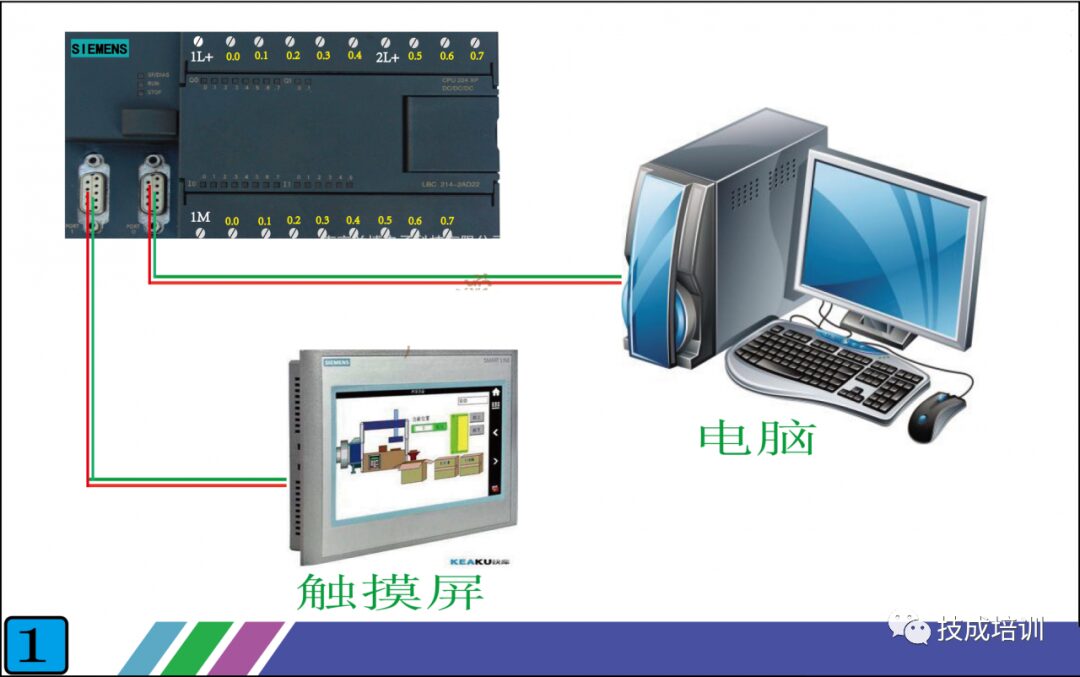
Figure 1
So what is the principle of communication between the touch screen and the PLC? Look at Figure 2 below, which shows the front and back of a real touch screen. The front is, of course, the display surface.
We mainly need to look at the back, which has three interfaces:
1. Power Interface: This supplies power to the touch screen, with a voltage typically of DC24V. The parameter label on the touch screen indicates this.
2. Configuration Download Interface: This is where we use the configuration software provided by the touch screen manufacturer to design the desired screens and functions on the computer, then download them to the touch screen via this interface. Each touch screen manufacturer has its own software, which is not universal, but that’s okay; the principles are the same. Once you learn one, you just need to familiarize yourself with the software interface of others.
3. Communication Interface: This interface is used for communication with the PLC. The forms of this interface mainly include RS232, RS485, and Ethernet (if you are unclear about 232 and 485, you can check my previous articles, which specifically introduce them). Here, it is important to note that the form of this interface must match the form of the PLC’s interface. The touch screen brand in Figure 2 is Kunlun Tongtai, and its interface is RS485, so when connecting to the PLC, the PLC’s interface must also be RS485.
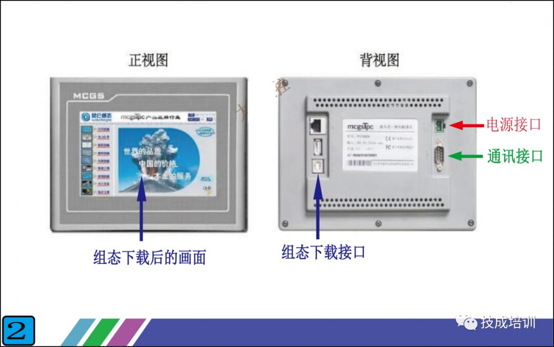
Figure 2
Having looked at the external aspects of the touch screen, let’s now examine its internal components. See Figure 3 below, which is a schematic diagram of the internal structure of a touch screen that I created myself. It may not be entirely comprehensive, but the important parts have been illustrated, and as long as you can understand it, that’s fine.
The internal structure of the touch screen can be roughly divided into: communication interface unit, drive unit, memory variable unit, and display unit. Except for the display unit, the other three units are not visible inside the touch screen.
1. Communication Interface Unit: This unit is mainly responsible for sending the data packets packaged by the drive unit to the communication interface on the back of the touch screen, which then sends them to the PLC. We do not need to intervene in this process; the touch screen will complete it automatically. Our task is to select a driver from the drive unit, essentially telling the touch screen which driver data packet to send.
2. Drive Unit: This unit stores many communication files for connecting to the PLC, with each file corresponding to a specific communication protocol (if you are not familiar with communication protocols, you can also check my previous articles). We refer to these files as drivers. In other words, a driver corresponds to a specific communication protocol. For example, if the Siemens S7-200 PLC uses the PPI communication protocol, then the touch screen manufacturer will write a file that can communicate with the Siemens S7-200 PLC PPI protocol and place it in the drive unit.
For instance, when our touch screen wants to connect with the Siemens 200 PLC, we select the PPI driver in the touch screen. If we want to connect to the Siemens 300 PLC, we simply select the MPI driver (MPI is the communication protocol for the Siemens 300 PLC). These driver files are pre-written by the touch screen manufacturer; we can only choose them and cannot modify them. Thus, the more drivers available in the touch screen, the broader the range of PLC brands or communication protocols we can choose from. Currently, established touch screen manufacturers have built-in drivers that can basically cover the commonly used PLCs and communication protocols in the market.
Therefore, when we have a touch screen and want to select a PLC for communication, we must check whether there is a driver in the touch screen that can communicate with this PLC.
3. Memory Variable Unit: This unit is also built-in by the touch screen manufacturer; it is essentially a storage area where various types of data can be stored, which can be roughly divided into numerical types, switch types, character types, and special types.
For example, if we want to display the water temperature of a boiler on the touch screen, we create a variable in the memory variable unit of the touch screen, naming it “Boiler Water Temperature” (the name can be arbitrary), and select the numerical type. The touch screen will automatically allocate a small area in the memory unit for this variable. When the touch screen communicates with the PLC, it will store the water temperature data read from the PLC in this small area, which is the variable “Boiler Water Temperature.” When we need to display multiple data points, we simply create multiple variables. You may still find this a bit confusing, but don’t worry; I will explain it systematically according to Figure 4 below, and you will understand it better.
4. Display Unit: This unit is straightforward; anything we can see on the touch screen is in the display unit. Taking the “Boiler Water Temperature” example, if we want to display the water temperature of the boiler, we just need to place a display component (which every touch screen has; you can directly drag it onto the screen) in the display unit and connect this component to the previously created variable “Boiler Water Temperature.”
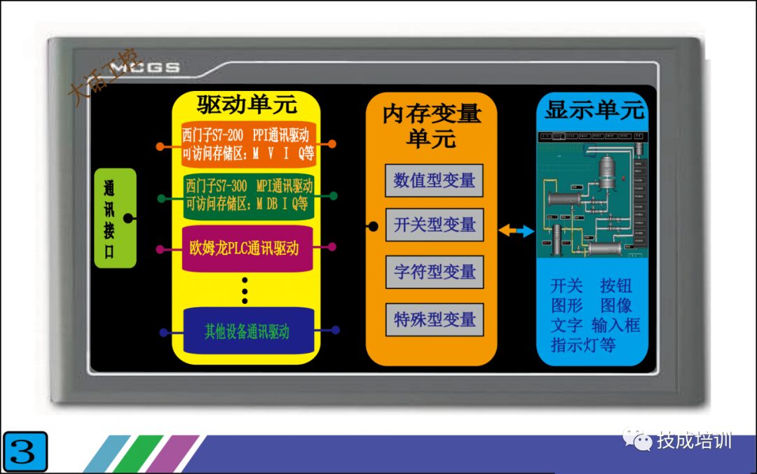
Figure 3
Having explained each unit, the most difficult to understand are the drive unit and memory variable unit. You might still be a bit unclear, but I will explain it systematically according to Figure 4, and you will be able to understand.
Figure 4 illustrates the functionality to be achieved: connecting the touch screen to the Siemens S7-200 PLC, 1. Displaying a pressure value from the PLC on the touch screen. 2. Controlling a switch quantity in the PLC through a switch component on the touch screen.
In the first step, we first select the driver in the touch screen because we are connecting to the Siemens S7-200 PLC, so we must choose the “Siemens S7-200 PPI communication driver” in the drive unit. Once the driver is selected, the touch screen will automatically connect the chosen driver with the communication interface unit and the memory variable unit. Next, let’s look at the internal structure of this driver (the orange part in Figure 4), which contains many addresses like V0.0, VB10, VW10, etc. These addresses correspond one-to-one with the addresses in the PLC, and the data and status inside are the same as those in the PLC. For example, if the data in PLC’s VD10 is 123.5, then the data in the touch screen’s VD10 will also be 123.5. Thus, the touch screen now has data, but this data still cannot be displayed because it has not yet been transmitted to the display unit. What should we do to make it visible?
In the second step, we create a variable in the memory variable unit called “Tank Pressure,” and we connect this variable with the VD10 in the drive unit. This way, the variable “Tank Pressure” will contain the data 123.5. However, the data still cannot be displayed because it has not been transmitted to the display unit.
In the final step, we place a display component in the display unit and connect this display component to the variable “Tank Pressure” in the memory variable unit. This way, we can see the data 123.5. It seems complex, but essentially what we need to do is connect these units through a newly created variable; everything else will be completed automatically by the touch screen.
Once you understand the workflow for displaying values on the touch screen, controlling the switch quantities becomes straightforward. Just place a switch component in the display unit, create a new variable, and connect it with the drive unit and display unit. As for how the touch screen sends this data to the PLC, you don’t need to worry; the communication interface unit will take care of that.
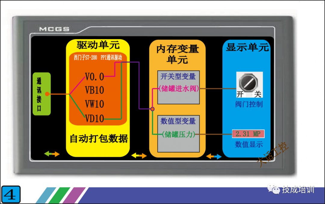
Figure 4
Figure 5 is the overall connection schematic, which represents the most basic combination. Through this PLC + touch screen combination, we achieve true human-machine dialogue. The data inside the PLC can be clearly seen, and by adding a few switch components on the touch screen, we can reduce the use of physical switches, thus minimizing the impact of poor contact of actual switch contacts on the control system and improving the stability of the system.
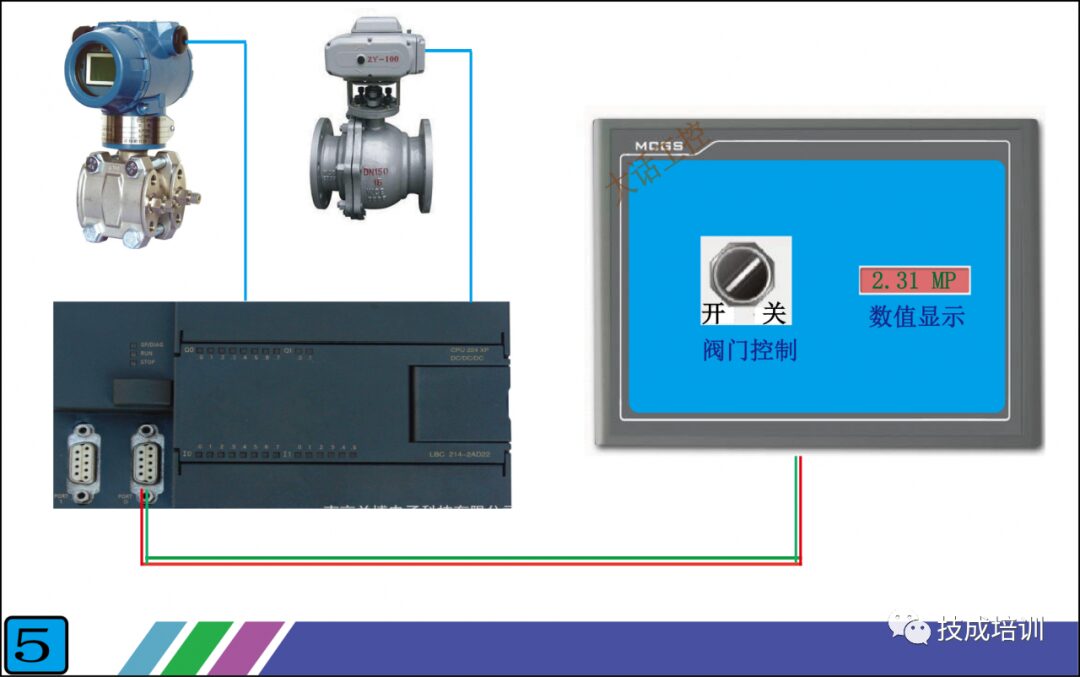
Figure 5
Source: Big Talk on Industrial Control, please delete if infringing