Click the blue text
Follow us
In practical control projects centered around PLCs, most of the time, we cannot do without the cooperation of touch screens or upper computers. This is because we use PLCs for control, mainly to process some analog quantities that we need to monitor, such as pressure, temperature, flow, and other values on the equipment. These detected values are then used to control electric valves, fans, pumps, etc., based on certain conditions. However, we cannot see these values directly from the PLC; to view them, we need to use a touch screen or an industrial computer (which is essentially a computer).
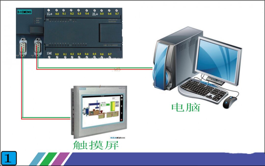
Figure 1
So what is the principle of communication between the touch screen and the PLC? Look at Figure 2 below, which shows the front and back of a real touch screen. The front is, of course, the display side.
We mainly focus on the back, which has three interfaces:
1. Power interface: This supplies power to the touch screen, with most voltages being DC24V. The parameter label on the touch screen indicates this.
2. Configuration download interface: This is where we use the configuration software provided by the touch screen manufacturer to design the desired screens and functionalities on the computer, and then download them to the touch screen via this interface. Each touch screen manufacturer has its own software, which is not interchangeable, but it doesn’t matter; the principles are the same. As long as you learn one, you can familiarize yourself with the interface of others.
3. Communication interface: This interface is used for communication with the PLC, and the types of interfaces mainly include RS232, RS485, and Ethernet (if you don’t understand what RS232 and RS485 are, you can refer to my previous articles, which introduce them specifically). It is important to note that the type of this interface must match the type of the PLC’s interface. The touch screen brand in Figure 2 is Kunlun Tongtai, and its interface is RS485, so when connecting to the PLC, the PLC’s interface must also be RS485.
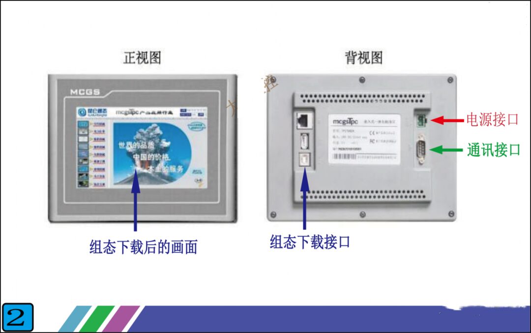
Figure 2
After looking at the external features of the touch screen, let’s take a look inside. Look at Figure 3 below, which is an internal schematic diagram of a touch screen that I made myself. It may not be very comprehensive or rigorous, but the important parts are already illustrated, and as long as you can understand it, that’s okay.
The internal structure of the touch screen can be roughly divided into: communication interface unit, driver unit, memory variable unit, and display unit. Except for the display unit, the other three units are not visible inside the touch screen.
1. Communication Interface Unit: This unit is mainly responsible for sending the data packets packaged by the driver unit to the communication interface on the back of the touch screen, which then sends them to the PLC. We do not need to intervene in this process; the touch screen will complete it on its own. What we need to do is select a driver from the driver unit, which essentially tells the touch screen which driver data packet to send.
2. Driver Unit: This unit stores many communication files that connect with the PLC, with one file corresponding to one communication protocol (if you don’t understand communication protocols, refer to my previous articles). We call these files drivers. In other words, a driver corresponds to a communication protocol. For example, if the Siemens S7-200 PLC uses the PPI communication protocol, then the touch screen manufacturer will write a file that can communicate with the Siemens S7-200 PLC using the PPI protocol and place it in the driver unit.
For instance, when our touch screen wants to connect with the Siemens 200 PLC, we select the PPI driver in the touch screen. If we want to connect with the Siemens 300 PLC, we choose the MPI driver (MPI is the communication protocol for Siemens 300 PLC). These driver files are pre-written by the touch screen manufacturers; we can only select them and cannot modify them. Thus, the more drivers a touch screen has, the wider the range of PLC brands or communication protocols we can choose from. The drivers built into mature touch screen manufacturers can basically cover commonly used PLCs and communication protocols on the market.
Therefore, when we have a touch screen and want to select a PLC for communication, we must check whether there is a driver in the touch screen that can communicate with this PLC.
3. Memory Variable Unit: This unit is also built into the touch screen by the manufacturer; it is essentially a storage area that can hold various types of data, which can be roughly categorized into numerical, switch, character, and special types.
For example, if we want to display the water temperature of a boiler on the touch screen, we would create a variable in the memory variable unit of the touch screen, naming it “Boiler Water Temperature” (the name can be arbitrary), and selecting the numerical type. The touch screen will automatically allocate a small area in the memory unit for the variable “Boiler Water Temperature.” When the touch screen communicates with the PLC, it will store the water temperature data read from the PLC in this small area, which corresponds to the variable “Boiler Water Temperature.” When we need to display multiple data points, we simply create multiple variables. If you still find this a bit hard to understand, don’t worry; I will explain it systematically with the help of Figure 4 below.
4. Display Unit: This unit is easy to understand; anything we can see on the touch screen is in the display unit. For example, to display the water temperature of the boiler, we simply need to drag a display component (which every touch screen has) onto the screen and connect it to the newly created variable “Boiler Water Temperature.”
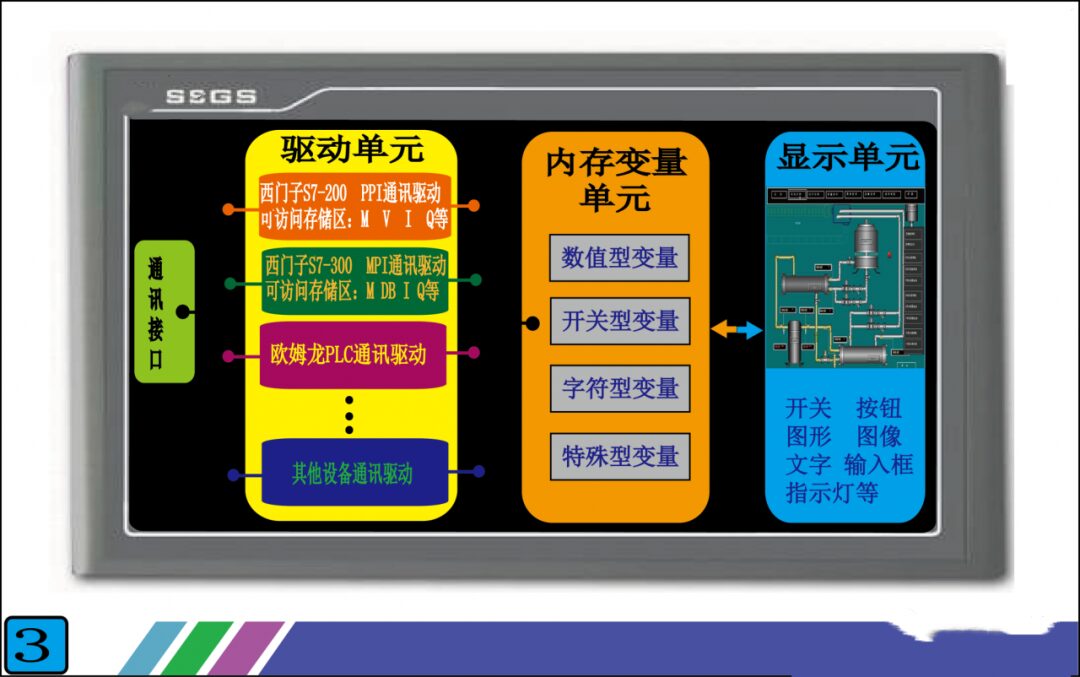
Figure 3
Having explained each unit, the most difficult to understand are the driver unit and the memory variable unit. You may still not fully grasp it, but I will explain it systematically with the help of Figure 4, and you will understand.
Figure 4 illustrates the functionality to be achieved: connecting the touch screen with the Siemens S7-200 PLC so that 1. A pressure value from the PLC can be displayed on the touch screen. 2. A switch component on the touch screen can control a switch quantity in the PLC.
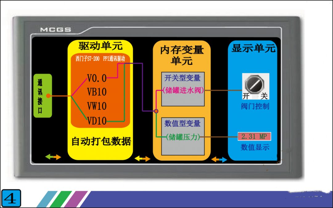
Figure 4
Step 1: First, we select the driver in the touch screen. Since we are connecting with the Siemens S7-200 PLC, we need to select the “Siemens S7-200 PPI Communication Driver” in the driver unit. Once the driver selection is complete, the touch screen will automatically connect the selected driver with the communication interface unit and the memory variable unit. Next, let’s take a look at the internal structure of this driver (the orange part in Figure 4), which contains many addresses like V0.0, VB10, VW10, etc. These addresses correspond one-to-one with the addresses in the PLC, and the data and states inside are the same as those in the PLC. For instance, if the data in PLC’s VD10 is 123.5, then the data in the touch screen driver’s VD10 will also be 123.5. Thus, the touch screen now has data, but this data still cannot be displayed because it has not been transmitted to the display unit. How can we resolve this?
Step 2: We create a variable in the memory variable unit called “Tank Pressure,” and we connect this variable to the VD10 in the driver unit. This way, the variable “Tank Pressure” will contain the data 123.5. However, the data is still not displayed because it has not been transmitted to the display unit.
Final Step: We place a display component with display functionality in the display unit, and then connect this display component to the variable “Tank Pressure” in the memory variable unit. This way, we can see the data 123.5. It seems quite complex, but essentially, all we need to do is create a new variable to connect these units, and the touch screen will complete the rest automatically.
Once you understand the workflow of displaying values on the touch screen, controlling switch quantities becomes straightforward. Just place a switch component in the display unit, create a variable, and connect it to the driver unit and the display unit. As for how the touch screen transmits these data to the PLC, you don’t need to worry; the communication interface unit will take care of that.
Figure 5 is the overall connection schematic. This is the most basic combination method. Through this combination of PLC and touch screen, true human-machine dialogue is achieved. The data inside the PLC is clearly visible, and by adding a few switch components on the touch screen, we can reduce the use of physical switches, thus minimizing the impact of poor contact on the control system and improving system stability.
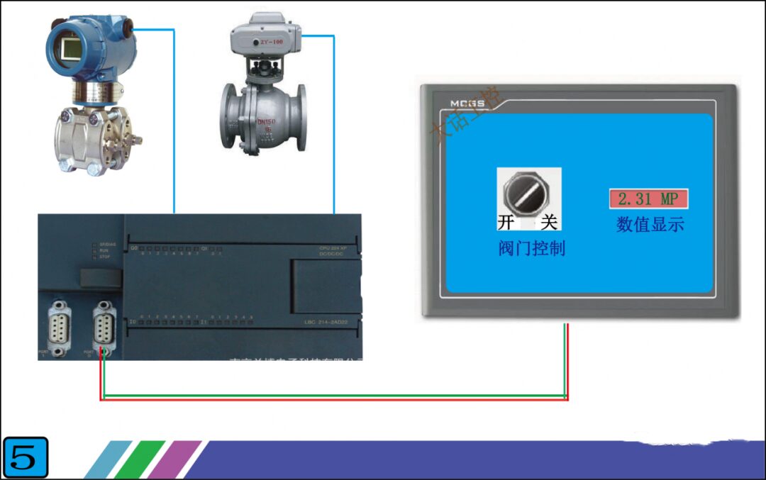
Figure 5
Source / Big Talk Industrial Control
Previous Issues · Recommendations
How to Simplify PLC Programs with Timers for the Same Function?
Wiring Diagram and Common Issues of S7-200 SMART PLC
A Guide to Connecting PLCs with Other Devices for Input and Output
Remember the Three Wires to Avoid Electric Shock!
Analysis of Schneider High-Power Inverter Maintenance
DCS Encyclopedia: Some Knowledge Every Industrial Control Person Must Know!
Stepper or Servo Motion Control Offset Issues: Phenomena, Causes, and Solutions

Share, View, and Like; at least I want to have one!