
How to Use PLC for Temperature Control
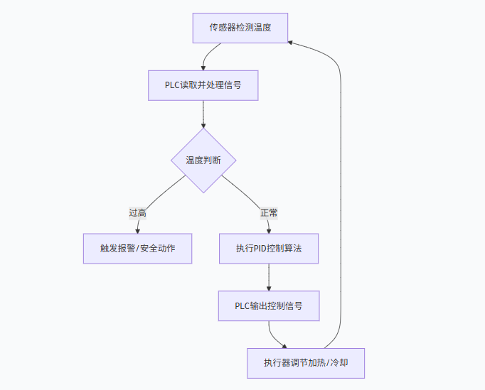
The entire control process can be summarized in the following core steps, and we will elaborate on this flowchart:
PART 01
Sensing Temperature
“How to signal when the temperature is high?”
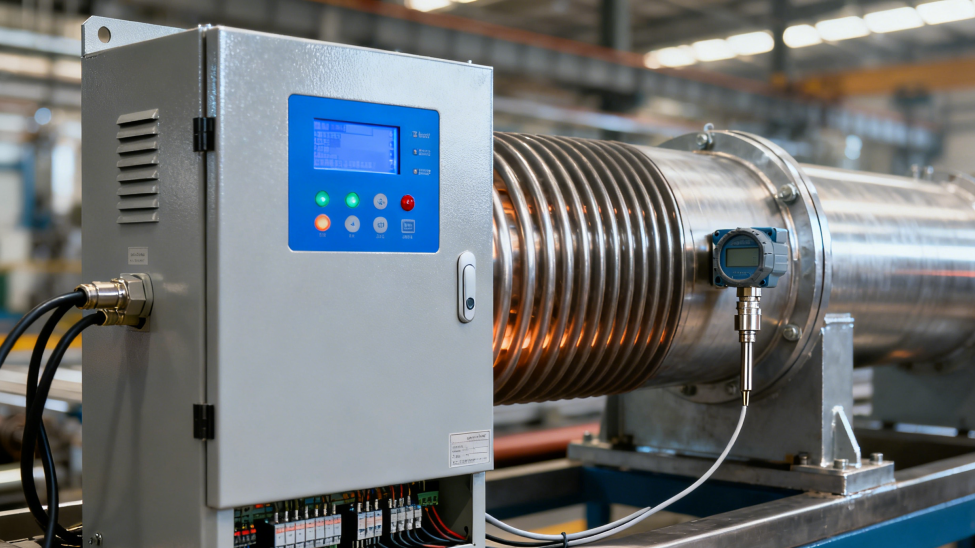
Core hardware: Temperature sensor and analog input module.
1
Temperature Sensors (Detection Elements)
-
Thermocouple: Suitable for high temperature ranges (e.g., 0℃-1200℃), the principle is that two different metals generate a small voltage (mV signal) related to temperature at the junction.
-
RTD (Resistance Temperature Detector), such as Pt100: Suitable for medium to low temperature ranges (e.g., -200℃-850℃), with high accuracy. The principle is that the resistance of the metal changes with temperature.
-
NTC/PTC Thermistor: Suitable for small range, low-cost applications, where resistance changes dramatically with temperature.
-
Non-contact Infrared Sensor: Used for measuring the surface temperature of objects that are inconvenient to touch.
2
Signal Transmission and Conversion (Making PLC Understand the Signal)
The signals generated by the sensors (resistance or small voltage) are very weak, and the PLC cannot read them directly. Therefore, it is necessary to:
-
Signal Conditioning and Conversion: Sensors are usually connected to a temperature transmitter. This device converts the sensor’s output signal into a standard, interference-resistant analog signal, most commonly: 4-20 mA current signal (industrial preferred, strong anti-interference, can detect line breaks); 0-10 V voltage signal.
-
PLC Interface: The PLC needs to be equipped with an analog input module to receive this standard signal. The core of this module is an analog-to-digital converter, which converts the continuous analog signal (e.g., 4-20 mA) into a digital value that the PLC CPU can process (e.g., 0-27648 or 0-16384, etc.).
3
Defining “High Temperature” in PLC
Assuming your control target is 100℃±5℃.
-
You set a setpoint = 100℃ in the PLC program.
-
At the same time, you can set an alarm upper limit = 105℃.
-
The PLC program continuously compares the read process value (current temperature) with these setpoints.
-
When the process value > 105℃, the PLC determines that “the temperature is high” and will execute the preset alarm action (such as lighting an alarm lamp, sounding a buzzer, displaying alarm information on the touchscreen).
PART 02
Decision Making
“How to ensure it stays within the control range?”
This is the core of the PLC program, ensuring the temperature remains stable within the target range.
1
Simple On/Off Control (Two-position Control)
-
Logic: Set a dead zone. For example, target 100℃.
When the temperature < 99℃, the PLC outputs a signal to start heating.
When the temperature > 101℃, the PLC outputs a signal to stop heating.
-
Disadvantages: Control is not precise, and the temperature will oscillate around the setpoint, suitable for less demanding situations (e.g., household water heaters).
2
PID Control (Proportional-Integral-Derivative)
– Industrial Standard Method
This is key to ensuring the temperature is stable, accurate, and quickly reached and maintained at the setpoint.
-
P – Proportional: The output control amount is proportional to the deviation between the current temperature and the setpoint. The larger the deviation, the stronger the control action. However, pure proportional control will have a steady-state error (cannot fully reach the setpoint).
-
I – Integral: Eliminates steady-state error. It accumulates historical deviations, and as long as there is a deviation, it continues to increase the control action until the deviation is zero.
-
D – Derivative: Controls based on the rate of change of the deviation, can predict future temperature trends, acting as a “brake” to prevent overshoot, making the system more stable.
3
How to Implement in PLC?
Almost all brands of PLCs provide ready-made PID instructions/function blocks.
-
You just need to call this function block in the program and connect: Input: Process value (PV, i.e., current temperature), setpoint (SP, i.e., target temperature); Output: Control amount (OUT, usually a value of 0.0-1.0 or 0-100%).
-
Core Work: PID Parameter Tuning. You need to adjust the values of P, I, and D parameters to achieve optimal performance of the control system. This is an empirical process.
PART 03
Executing Commands
“How to achieve controlled temperature?”
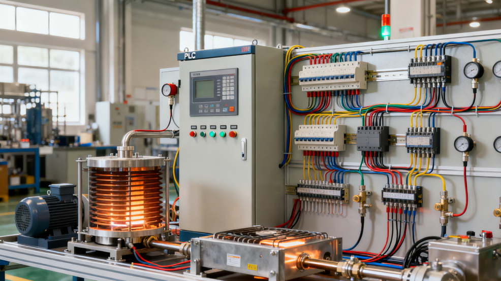
Core hardware: Actuator and PLC output module.
After PID computation, the PLC obtains a control amount (e.g., “heating power needs to be 50%”), and this instruction needs to be transmitted to the actuator through the output module.
1
Output Signal Types
-
Analog Output: The PLC’s analog output module generates a standard 4-20 mA or 0-10 V signal to control the actuator.
-
Digital Output (Switching Signal): Combined with Pulse Width Modulation technology, it equivalently produces a continuous average power through rapid switching.
2
Actuators (Devices for Final Actions)
Controlling Heating:
-
Solid State Relay: This is the most common method. The PLC’s output signal (or through an intermediate relay) controls the conduction angle of the SSR, thereby controlling the average power applied to the heating element, achieving voltage/power regulation.
-
Thyristor (SCR) Voltage Regulator: Used for high-power precision heating control.
-
Contactor: Simple switching control, requires PWM function when used with PID.
Controlling Cooling:
-
Electromagnetic Valve/Electric Control Valve on the cooling water/air duct (receives analog signals, adjusts opening).
-
Directly controlling the fan/pump start/stop or using a frequency converter (to adjust speed).

“Beckman, exploring a broader clean world with you!”