
Recommended: 1. Share and Download | Complete Materials for Yaskawa, KUKA, ABB, FANUC!
2. 【15G】Free Siemens 200/300/1200/1500 PLC Video Tutorial Available! Limited to 200 people
3. Limited Time Download | 【10G】Complete Video Tutorials for Mitsubishi, Siemens, Omron PLC!
Methods for Mitsubishi PLC to Control Mitsubishi Inverters:
Using the PLC’s digital output to control the inverter (i.e., connecting the PLC’s digital output directly to the inverter’s digital input, allowing the PLC to control the inverter’s start, stop, forward/reverse rotation, and multi-segment speed operation at high, medium, and low speeds through programming).
Using the PLC’s analog signal to control the inverter.
The PLC controls the inverter using the RS-485 Modbus-RTU communication method.
The PLC controls the inverter using fieldbus methods.
The PLC controls the inverter using RS-485 unprotocol communication methods.
Among these, the RS-485 unprotocol communication method to control the inverter has been widely used. In the RS-485 unprotocol communication method for controlling the inverter, the PLC is programmed to control through RS serial communication instructions.
1. System Configuration
The hardware configuration of the system includes:
One FX2N series PLC (product version V3.00 or above);
One FX2N-485-BD communication board (maximum communication distance 50m) or one FXON-485ADP + one FX2N-CNV-BD board (maximum communication distance 500m);
Mitsubishi inverters with RS-485 interfaces (F700 series, S500 series, E500 series, F500 series, A500 series), which can be mixed but the total quantity does not exceed 8 units.
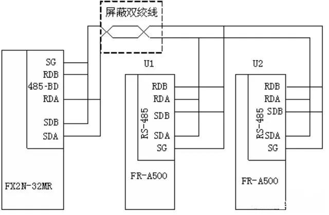
The connection between the PLC and the inverter is made using a network cable, specifically connecting the RJ45 plug of the network cable to the PU socket of the inverter.
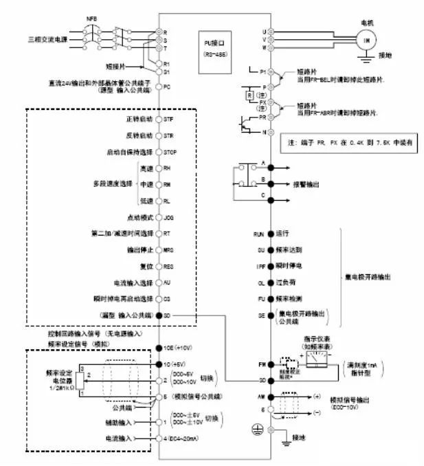
2. Mitsubishi FR-A500 Series Inverter
1. FR-A500 Inverter Terminal Wiring Diagram
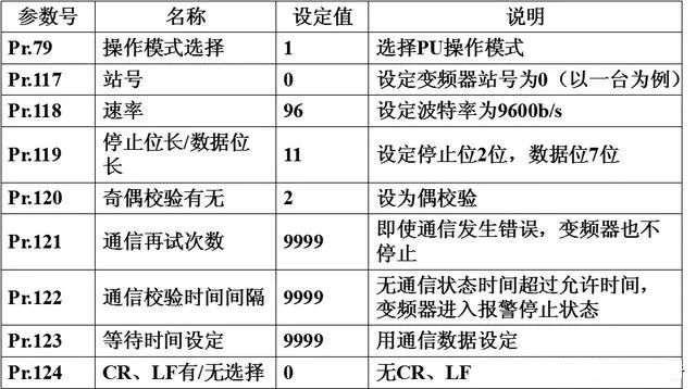
2. FR-A500 Inverter Communication Parameter Settings
To establish communication correctly, parameters related to communication must be set on the inverter, such as station number, communication rate, stop bit length/word length, and parity check.
The parameters Pr.117 to Pr.124 in the inverter are used to set communication parameters.
Parameter settings can be done using the operation panel or the inverter setup software FR-SW1-SETUP-WE at the PU port.
FR-A500 Communication Parameter Settings
3. FR-A500 Inverter Data Format
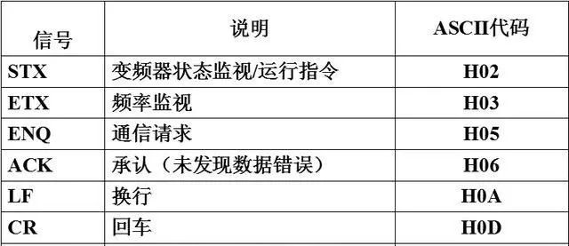
Using hexadecimal numbers, data is automatically transmitted between the PLC and the inverter using ASCII code.
1) Communication request data format from PLC to inverter
If the inverter communication parameter is set to no LF/CR, then the total number of ASCII characters for communication data sent from PLC to inverter is 12 (in format A).
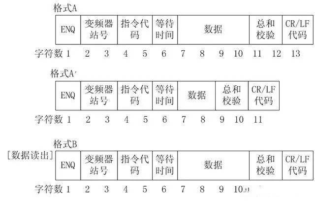
2) Input data format from inverter to PLC
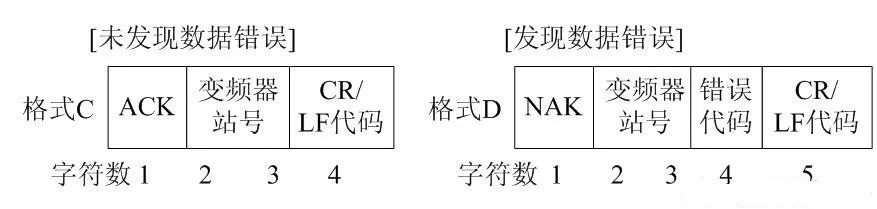
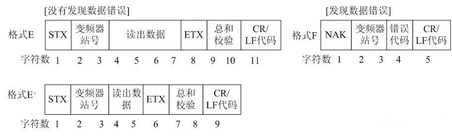
3) Response data format from inverter to PLC when reading data
If the inverter communication parameter is set to no LF/CR, the total number of ASCII characters read from the inverter at once is 10 (when no errors are found).
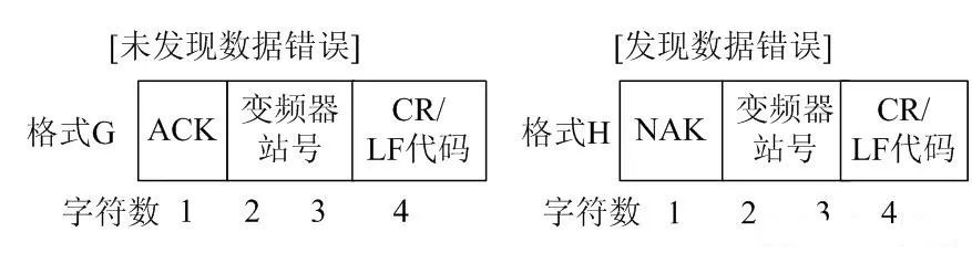
4) Data format sent from PLC to inverter when reading data
The above data formats refer to the data transmitted between the PLC and the inverter (such as frequency and parameters).
The waiting time is defined as the time the inverter waits between receiving data from the PLC and transmitting response data. The waiting time is set based on the PLC’s response time, between 0 to 150ms, with a minimum setting unit of 10ms. If the Pr.123 parameter unit of the inverter is not set to 9999, then the waiting time is not set by the communication data, and there is no waiting time in the communication data format (missing one character).
The checksum is represented by the lowest byte (8 bits) of the total sum (binary) of the ASCII data being checked, expressed as two ASCII digits (hexadecimal).
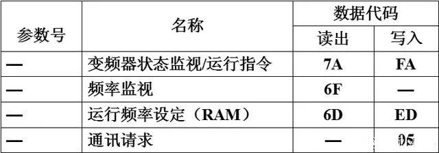
4. Control codes and instruction codes for FR-A500 inverter
FR-A500 control code description
Instruction codes sent from the PLC to the inverter indicate the program requirements (e.g., run, monitor, etc.). With the corresponding instruction codes, the inverter can operate and monitor in various ways.
FR-A500 instruction code description
3. Communication Program Design
1. Special Data Registers
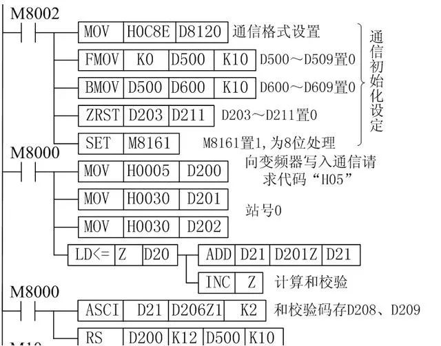
(1) D8120 sets the data communication format
Set data length to 7 bits, even parity, 2 stop bits, baud rate of 9600b/s, no header or terminator, no added and check code, using unprotocol communication (RS-485). Thus, D8120 is set as: b15~b0=0000 1100 1000 1110=0C8EH.
(2) D8122 stores the bytes of information that have not yet been sent.
(3) D8123 stores the number of bytes received.
(4) D8124 is the start symbol (8 bits) initial value STX (02H)
(5) D8125 is the end symbol (8 bits) initial value EXT (03H)
(6) D8129 sets the data network timeout timer value. The unit is 10ms
2. Communication Program
Set the inverter station number to 0, data length to be transmitted is 7 bits, even parity, 2 stop bits, baud rate of 9600b/s, no header or terminator, no added and check code, using unprotocol communication (RS-485).
M10 on controls the inverter to enter forward rotation state, M11 on controls the inverter to enter stop state, M12 on controls the inverter to enter reverse state, M13 on reads the inverter’s operating frequency (D700~D703), M14 on writes the operating frequency to the inverter (D400~D403).
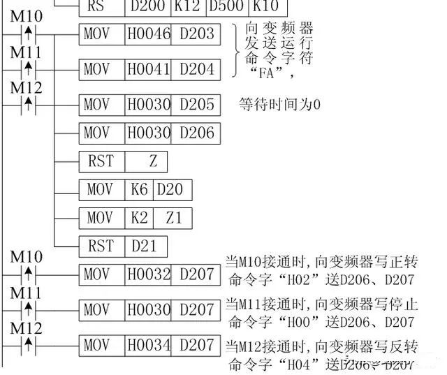
When any of M10, M11, or M12 is on, the PLC first sends the running control signal to the inverter. D200~D209 are the addresses for sending data, where D200 stores the communication request code 05H, D201, D202 store the inverter station number 0, D203, D204 store the instruction code (run command word FAH), D205 stores the waiting time (0ms), and D206~D207 store the sending data (D206, D207 store forward 02H/reverse 04H/stop 00H), D208~D209 store the checksum.
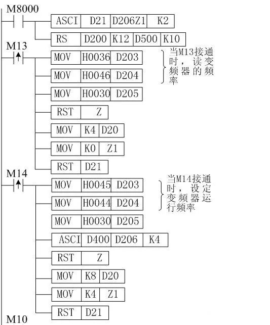
When M14 is on, the PLC sends the operating frequency to the inverter. Assuming the operating frequency is stored in D400~D403, D200~D211 are the addresses for sending data, where D200 stores the communication request code 05H, D201, D202 store the inverter station number 0, D203, D204 store the instruction code (write operating frequency command word EDH), D205 stores the waiting time (0ms), D206~D209 store the sending data (operating frequency), D210~D211 store the checksum.
When M13 is on, the PLC sends the control signal to read the inverter’s operating frequency. D200~D207 are the addresses for sending data, where D200 stores the communication request code 05H, D201, D202 store the inverter station number 0, D203, D204 store the instruction code (read operating frequency command word 6DH), D205 stores the waiting time (0ms), D206~D207 store the checksum.
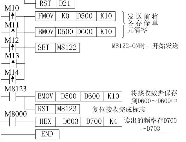
D500~D509 are the addresses for receiving data, and D600~D609 are the storage addresses for the received data.
Disclaimer: This article is a network reprint or adaptation, and the copyright belongs to the original author. If there are copyright issues, please contact to delete!
Follow and subscribe to this public account to learn automation technologies such as robots, PLCs, touch screens, configuration, inverters, servo control, sensors, and pneumatics, and easily become an excellent automation engineer.

Long press to recognize the QR code and follow the public account!
↓↓↓ Click “Read the original text” 【See more information】