
San Pao Er’s Hardware Development Learning Notes
Sharing knowledge to enhance skills♥Exchanging experiences to strive for excellence

Table of Contents
✍
RS-485 is a balanced transmission standard for serial communication approved by the Electronic Industries Alliance (EIA) in 1983. As an electrical standard, RS-485 defines only the electrical characteristics of drivers and receivers using balanced multipoint transmission lines; many higher-level standards reference RS-485 as a reference standard, such as Modbus, Profibus, and DL/T645.
1.Main Features
2.Network Topology
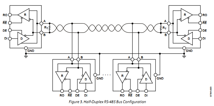
RS-485 recommends using a daisy chain to connect its nodes, with drivers, receivers, and transceivers accessing the trunk line through short stubs, as shown in the figure below.

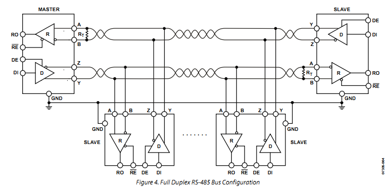
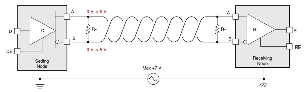
The RS-485 interface bus can be designed for full-duplex or half-duplex transmission modes, as shown in the figure below.

The RS-485 standard specifies that the driver can provide a differential output of no less than 1.5V under a 54Ω load, while the receiver can detect differential inputs as low as 200mV;
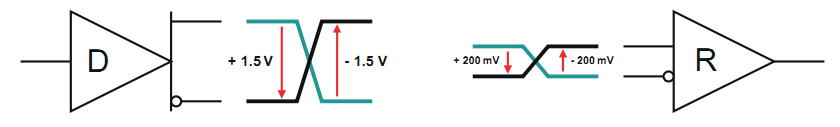
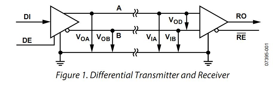
If the input terminal of the transmitter receives a logic low level (DI=0), then the driver outputs with the A line voltage less than the B line, and VOA-VOB≤-1.5V;
If the voltage of the A line at the receiver input is less than the B line, and VIA-VIB≤-200mV, then the receiver outputs a logic low level (RO=0)
2. Unit Load
A driver must be able to drive a minimum of 1.5V differential signal through two 120Ω termination resistors in parallel with up to 32 unit loads;
To determine the unit load parameter, the input voltage on one bus pin is swept from -7V to 12V, while the other bus pin remains grounded, and the input leakage current is measured;
The -7V and 12V levels in the standard are to allow for a ground potential difference (GPD) of up to ±7V between the driver output and the receiver, with the driver’s output voltage varying between GND and 5V;
-7V represents that the receiver is driven by the driver to the low level of the bus with -7V GPD;
And 12V represents that the receiver is driven by the driver to the high level of the bus with 7V GPD;
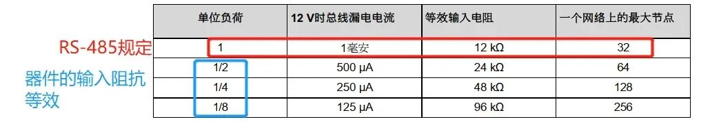
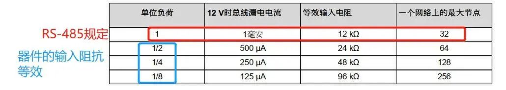
Some RS-485 receivers support 1/4 or 1/8 unit loads, allowing for more transceivers to be connected;
The relationship between unit load and receiver input impedance is shown below:
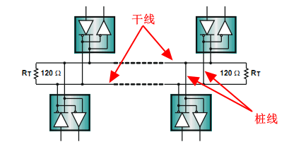
Good termination requires that the termination resistor RT matches the characteristic impedance Z0 of the transmission line;
The RS-485 standard recommends a characteristic impedance Z0 of 120Ω for the transmission line;
As shown in the figure below, cables typically use 120Ω resistors for termination.
The length of the stub (branch) can be calculated using the following formula:
Lstub = tr/10 * v * c
Lstub = Maximum stub length (inch)
tr = Driver (10/90) rise time (ns)
v = The transmission speed of the signal on the trunk cable as a ratio of the speed of light
The transmission speed of signals on PCBs made from Fr4 material is half the speed of light
c = Speed of light (12 inch/ns)
For example::
As shown in the figure, the driver output rise time of MAX13488E is 15ns
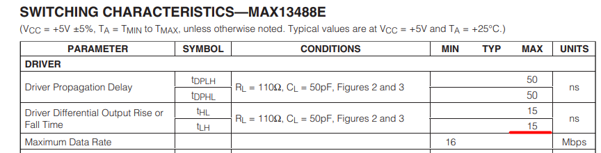
Substituting gives:
Thus, the stub length cannot exceed 22.86 cm
Causes of lack of input signal include the following three:
① Open circuit: cable interruption or transceiver disconnection from the bus
② Short circuit: wires of the differential pair contact each other due to insulation failure
③ Bus idle: this occurs when all bus drivers are inactive.
Under the above conditions, when the input signal is zero, traditional receivers output random states;
Currently, most transceivers internally include a fail-safe biasing circuit to protect against open circuit, short circuit, and bus idle, ensuring that even when the signal is lost, the receiver can force output to a definite state.
However, some fail-safe protection designs also have their drawbacks, with the worst-case noise margin being only 10mV;
Therefore, in noisy environments, it is necessary to add external fail-safe biasing circuits to increase noise margins.
The above explanation of fail-safe biasing is relatively general and not detailed enough; below is a detailed explanation of fail-safe biasing by ADI.
1. Bus Idle State – Receiver Output RO May Be Incorrect
The UART communication data format is: start bit + data bits + parity bit + stop bit;
The start bit is detected when the transition from high to low occurs, followed by 8 data bits, 1 parity bit, and stop bits (1 or 2); then another start bit;
When the last character is sent, the line should remain high until the next start bit.
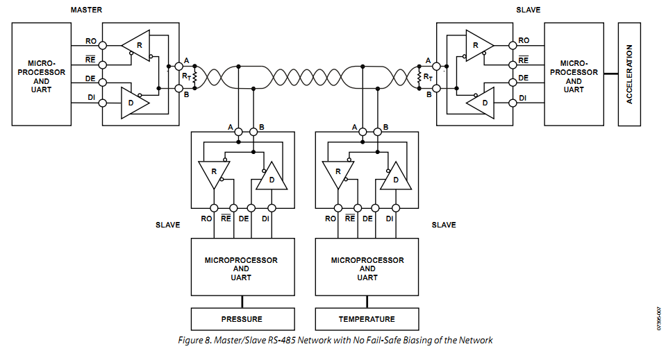
There is a state called bus idle state, which occurs when all transceivers connected to the bus are in receive mode at the same time; during this state, the differential voltage on the bus (VOA−VOB) is 0V.
For an RS-485 network without fail-safe biasing circuits,
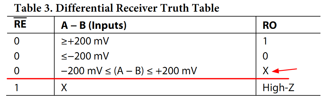
in the bus idle state, the receiver RO output is not defined by the RS-485 standard (as shown in the figure Differential Receiver Truth Table)
and the receiver RO output generates random data, which may lead to system operation errors.
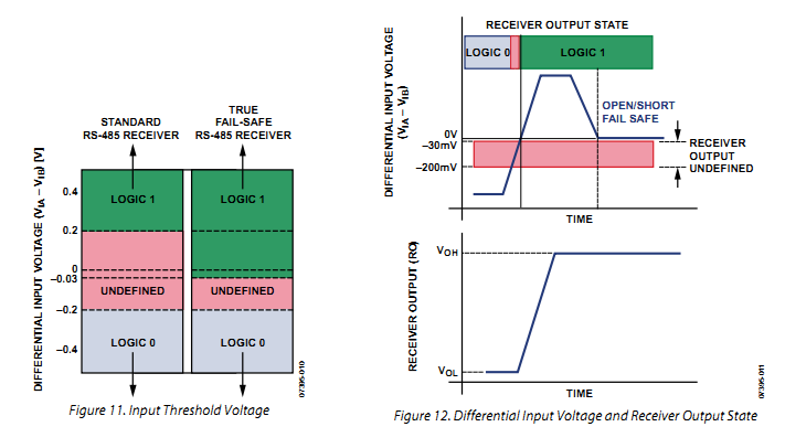
2. Differential Input Threshold Voltage
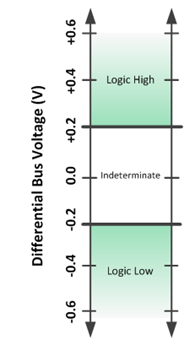
As mentioned earlier, the RS-485 standard specifies a ±200mV differential input threshold voltage; when the differential input VIA-VIB≥200mV, the receiver outputs a logic high level (RO=1);
When the differential input VIA-VIB≤-200mV, the receiver outputs a logic low level (RO=0);
This means that the differential input voltage has a 400mV uncertain state, as shown in the figure.
Two of the most commonly used methods are:
① Using receivers with built-in fail-safe input thresholds;
② Creating an external bias on the idle bus using additional external resistors;
Both methods ensure a logic high state on the bus, equivalent to a positive differential voltage.
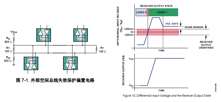
3. Receivers with Built-in Fail-Safe Input Thresholds
As shown in the figure, receivers with built-in fail-safe input thresholds adjust the differential input threshold voltage from ±200mV to −200 mV and then to −30 mV through internal bias circuits;
Even in the bus idle state where VOA-VOB=0 (>-30mV), the receiver RO output is high.
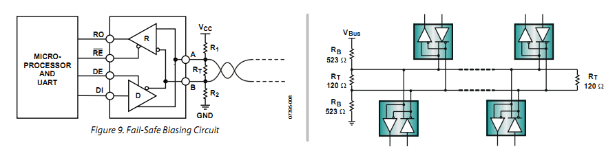
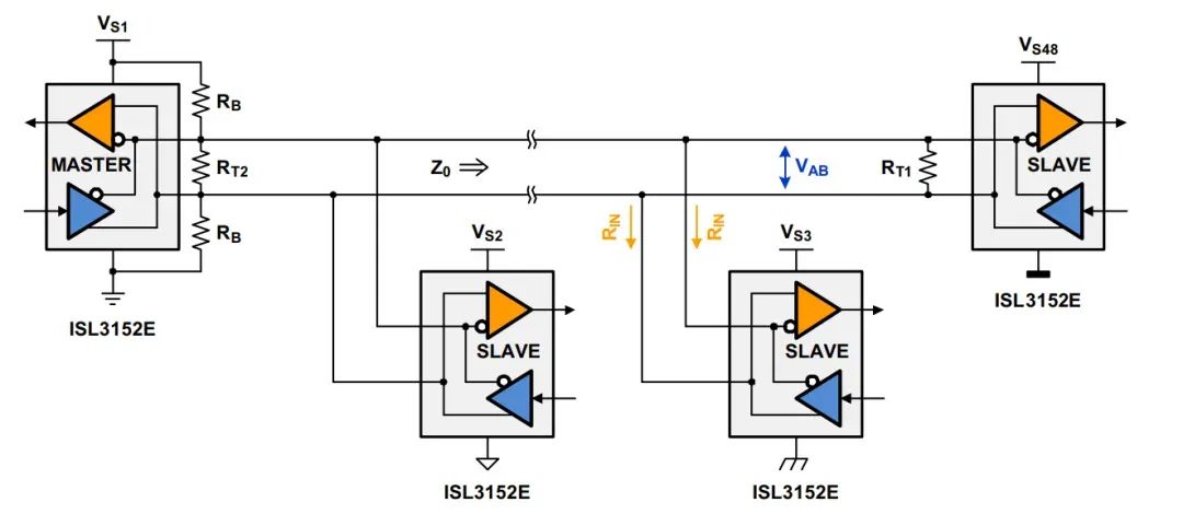
4. External Fail-Safe Biasing Circuit
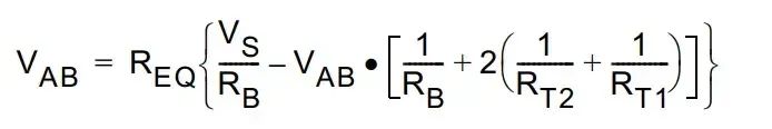
The external fail-safe biasing circuit consists of a resistor voltage divider that can generate sufficient bus differential voltage to drive the receiver to produce a definite output state.
To ensure sufficient noise margin, in addition to the 200mV receiver input threshold, VAB must also include the maximum measured differential noise, VAB= 200mV + Vnoise.
For applications with transmission distances less than 100 meters, bias circuits are typically provided at one end of the bus, as shown in the figure below.
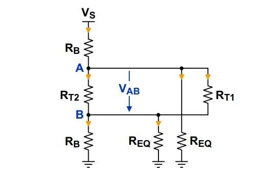
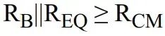
To calculate the value of the external biasing resistors, it is necessary to ensure that the line termination and common mode load meet the following conditions:
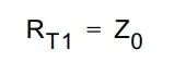
① The cable end without a bias network uses RT1 for termination, with a value equal to the cable’s characteristic impedance Zo, i.e.

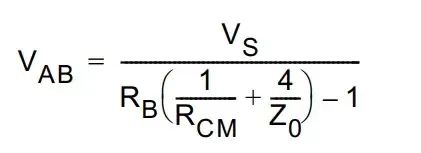


Zo=120Ω, minimum supply voltage is 4.75V (5V supply, ripple 5%) Vab=300mV (designed according to 200mV+100mV noise margin)

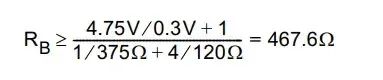
Select standard resistor RB=470Ω
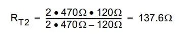
Select standard resistorRT2 = 138Ω
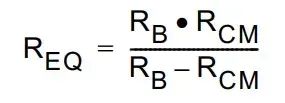
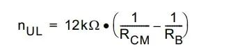
nul is the ratio of one unit load to the input impedance of the transceiver: nul=12KΩ/REQ
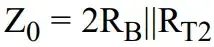
Then:
Based on the above calculation RB=470Ω, then
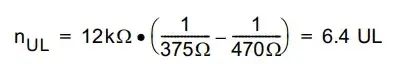
If the input impedance of the transceiver is 1/8UL, it can connect 6.4/1/8 = 51 units

Finally

More Notes
RS-232
Introduction to Common Level Conversion Circuits
Understanding SPI Interface in One Article
Understanding I2C Bus in One Article
Understanding the Differences and Design Selection of Crystal Oscillators and Crystals in One Article
Understanding the Power-Up Timing of Xilinx Zynq7000 and 7 Series FPGA in One Article
Understanding the Bootstrap Capacitor of BUCK Circuits in One Article
What are the Differences Between LDO and DCDC?
Understanding the Basics of DCDC in One Article
Understanding the Basics of LDO in One Article
What Research is There on Pull-Up and Pull-Down Resistors?
Why is it Common to Place 1uF and 0.1uF Capacitors in Parallel in Circuits?

This is Soft Grinding HardFollow the WeChat public account, the owner San Pao Er’s Hardware Development Learning Notes and Experience Sharing
Learning Sharing knowledge to enhance skills, exchanging experiences to strive for excellence