The RS-485 bus is widely used in industrial communication, but harsh industrial environments can lead to external interference, such as Electrical Fast Transients (EFT), which affect its stability. This article explores how to test and mitigate the interference of EFT on the RS-485 bus.
 Sources of Pulse Group Interference
In industrial control environments, disturbances often arise from lightning, short circuits, and switching actions involving inductive loads, producing instantaneous interference. These disturbances manifest as brief, high-energy pulse interferences characterized by clusters of pulses, short rise times, and high repetition frequencies. These interferences can couple onto the RS-485 bus, and since they are not isolated pulses but rather a series of pulses, they accumulate on the RS-485 bus, causing the disturbance voltage amplitude to exceed the noise tolerance of the RS-485 transceiver, leading to communication errors.
Sources of Pulse Group Interference
In industrial control environments, disturbances often arise from lightning, short circuits, and switching actions involving inductive loads, producing instantaneous interference. These disturbances manifest as brief, high-energy pulse interferences characterized by clusters of pulses, short rise times, and high repetition frequencies. These interferences can couple onto the RS-485 bus, and since they are not isolated pulses but rather a series of pulses, they accumulate on the RS-485 bus, causing the disturbance voltage amplitude to exceed the noise tolerance of the RS-485 transceiver, leading to communication errors.
Moreover, due to the short cycle of these pulse disturbances, the intervals between individual pulses are brief. When the first pulse disturbance has not yet dissipated, the second pulse follows closely. For the parasitic capacitance on the RS-485 bus and the junction capacitance of the RS-485 transceiver, charging begins again before the previous discharge is complete. Typically, the parasitic capacitance is small, and even a small amount of energy can reach a high voltage, which can easily damage the RS-485 transceiver and affect the reliability of RS-485 bus communication.
 Principle of Pulse Group Interference Generation
The voltage of the pulse group interference source depends on factors such as the inductance of the load circuit and the speed of load disconnection. Taking switching actions as an example, when the switch opens, the distance between the dynamic and static contacts is relatively close, and the back electromotive force induced by the inductance in the circuit is sufficient to break down the air gap between the contacts, causing the circuit to conduct. However, this discharge process is very brief, resulting in a leading edge pulse in the nanosecond range, with a width of several tens of nanoseconds and a voltage amplitude exceeding several kilovolts.
Principle of Pulse Group Interference Generation
The voltage of the pulse group interference source depends on factors such as the inductance of the load circuit and the speed of load disconnection. Taking switching actions as an example, when the switch opens, the distance between the dynamic and static contacts is relatively close, and the back electromotive force induced by the inductance in the circuit is sufficient to break down the air gap between the contacts, causing the circuit to conduct. However, this discharge process is very brief, resulting in a leading edge pulse in the nanosecond range, with a width of several tens of nanoseconds and a voltage amplitude exceeding several kilovolts.
Once the pulse ends, the circuit begins to repeat the process of inductive load generating back electromotive force and discharging through the air gap between the switch contacts. This process continues until the energy stored in the inductive load is sufficiently low to prevent further discharges. These disturbances couple onto the RS-485 bus, creating significant interference that impacts communication reliability.
 Measures to Improve EFT Immunity
EFT immunity is a common mode interference that can be suppressed through filtering, absorption, or isolation methods.
Measures to Improve EFT Immunity
EFT immunity is a common mode interference that can be suppressed through filtering, absorption, or isolation methods.
1. Isolation of the RS-485 Bus
Adding isolation in the circuit is one of the most common measures to enhance bus immunity. For example, the isolation RS-485 transceiver modules from Zhiyuan Electronics, such as RSM485PHT (automatic send/receive), RSM485MG, RSM485JCHT, and RSM485ECHT, integrate signal isolation and power isolation functions. Without an external protection circuit, they can achieve IEC 61000-4-4 ±2kV (Level B, tested with the RS-485 port floating). For higher levels of protection, additional measures can be implemented based on actual conditions. As shown in Figure 1, the RSM3485PHT isolation transceiver module underwent EFT testing without additional protection circuits, successfully passing IEC 61000-4-4 ±2kV (Level B).
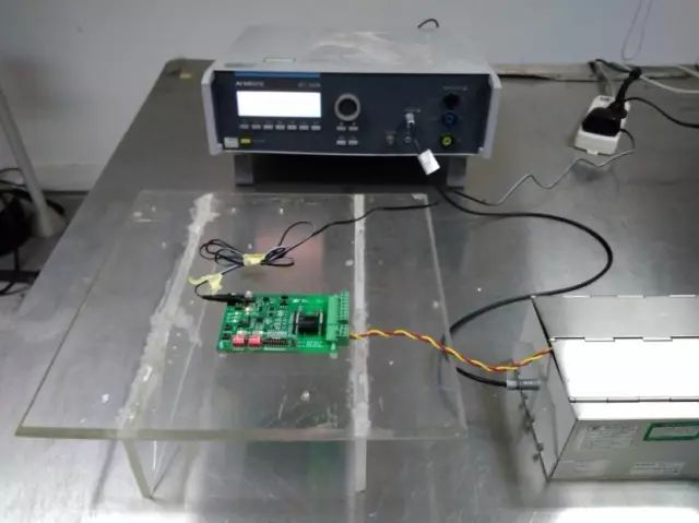
Figure 1 RSM3485PHT Module EFT Test
2. Adding Ferrite Beads to Absorb Interference
Installing ferrite beads at the device entry point can effectively absorb interference. Additionally, increasing the number of turns of the communication line through the ferrite beads can enhance the absorption effect, as shown in Figure 2, where ferrite beads are added near the RS-485 interface of the device under test.
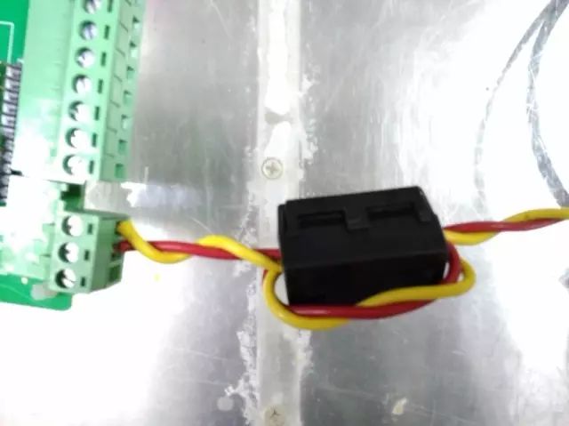
Figure 2 Adding Ferrite Beads to Communication Line
3. Using Shielded Twisted Pair
As shown in the figure, in practical applications, RS-485 communication lines can utilize shielded twisted pairs, with the shield connected to ground at a single point to effectively suppress the coupling of EFT interference onto the communication line.
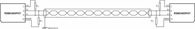
Figure 3 Using Shielded Twisted Pair
4. Adding TVS to Ground on RS-485 Bus
By adding a TVS diode between A to ground and B to ground, when high voltage EFT interference is coupled onto the RS-485 bus, the interference voltage will be clamped by the TVS, protecting the RS-485 transceiver.
5. Series Ferrite Beads on RS-485 Bus
Since ferrite beads act as resistors at high frequencies, they convert high-frequency energy into thermal energy, thus when ferrite beads are placed in series on the RS-485 bus, the energy of the EFT signal coupled onto the RS-485 bus will be dissipated by the ferrite beads, enhancing the anti-interference capability of the RS-485 bus.
 Examples of Improving EFT Immunity Levels
As shown in Figure 4, the circuit with two RSM3485PHT modules with series ferrite beads on interfaces A and B can achieve IEC 61000-4-4 ±4kV, effectively reducing the communication error rate. By simply adding ferrite beads in series in the circuit, it is a very cost-effective measure. If a higher level of EFT immunity is required, the number of ferrite beads can be increased appropriately.
Examples of Improving EFT Immunity Levels
As shown in Figure 4, the circuit with two RSM3485PHT modules with series ferrite beads on interfaces A and B can achieve IEC 61000-4-4 ±4kV, effectively reducing the communication error rate. By simply adding ferrite beads in series in the circuit, it is a very cost-effective measure. If a higher level of EFT immunity is required, the number of ferrite beads can be increased appropriately.
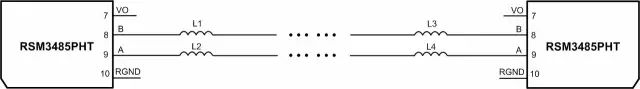
Figure 4 Series Ferrite Beads on Communication Line
Isolation RS-485 Transceiver RSM485PHT
• Miniature size or standard modular packaging
• Low electromagnetic radiation and high magnetic interference resistance
• Effectively enhances bus communication protection level