MAKER:jocomakerspace / Translated by: 趣无尽
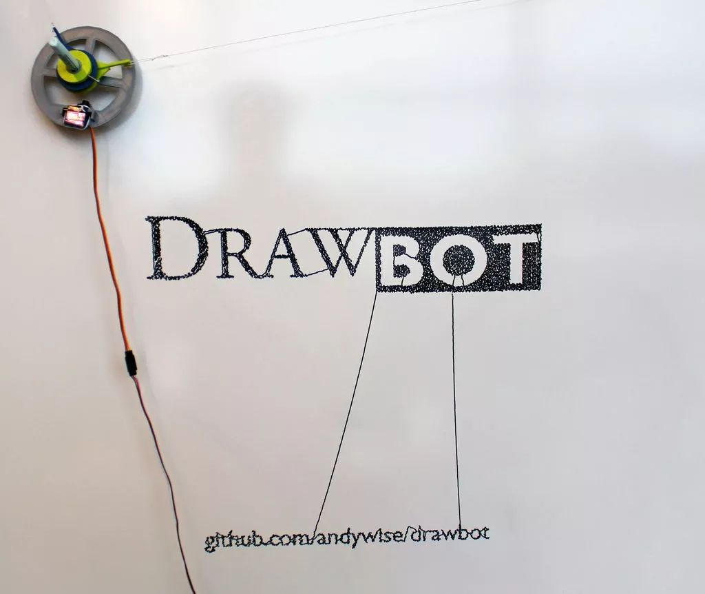
This project introduces a drawing machine that can draw large-scale graphics directly on an upright canvas, making the drawing process quite visually appealing. The core system is built using a Raspberry Pi and supports receiving patterns via WIFI. First, let’s take a look at a test video.
Materials List
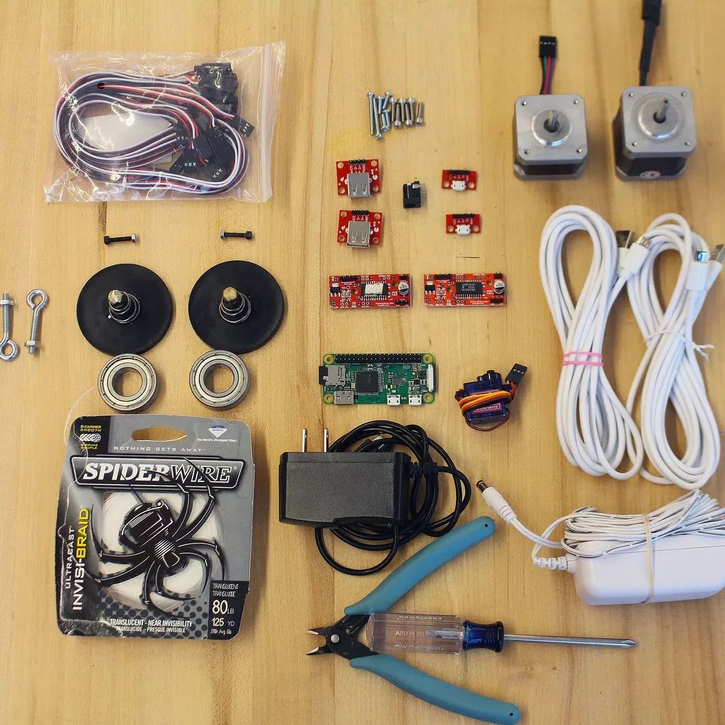
HardwareNEMA 17 stepper motors x2, suction cups x2, 80 lb fishing line x several, Micro USB cables x2, Micro USB adapter boards x2, USB A female adapter boards x2, Raspberry Pi (Raspberry Pi) Zero W, Micro SD card, EasyDriver stepper motor driver board V4.5 x2, SG92R servos x1, 6003zz bearings x2, 23-pin motor expansion board x several, 2.1mm x 5.5mm socket x1, power adapter 12v 1a with 2.1mm or 5.5mm connector x1, Raspberry Pi power adapter x1, Pololu universal wheel axle 5mm (#4-40 hole) x2, bolts (#8-32 x 1-5/8 inches) x2, screws (#4-40 x 1/2 inch) x8, motor screws (M3 50 x 6mm motor screws) x8, small screws x2 (for securing pen/marker), standard wire or jumper wire x several, marking pens x1, tape measure or ruler x1
ToolsComputer, soldering iron x1, pliers/cutter x1
Optional MaterialsPaper x several, USB fan x1, hot glue x1, paper clips x1, header pins x1, breadboard/circuit board x1
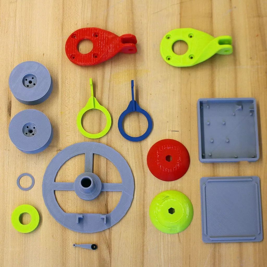
3D Printed Components
Polargraph gondola
Servo horn extension
Drawbot motor mount and spool (x2)
Drawbot electronics case (optional)
Drawbot Pi + Stepper mount (optional)
Suction Cup Dome with hole (optional)
The above design files are available for download in this project repository. (Friends without a 3D printer can find 3D printing studios on Taobao if needed)
http://maker.quwj.com/project/80
Installation of Stepper Motors and Suction Cup Components
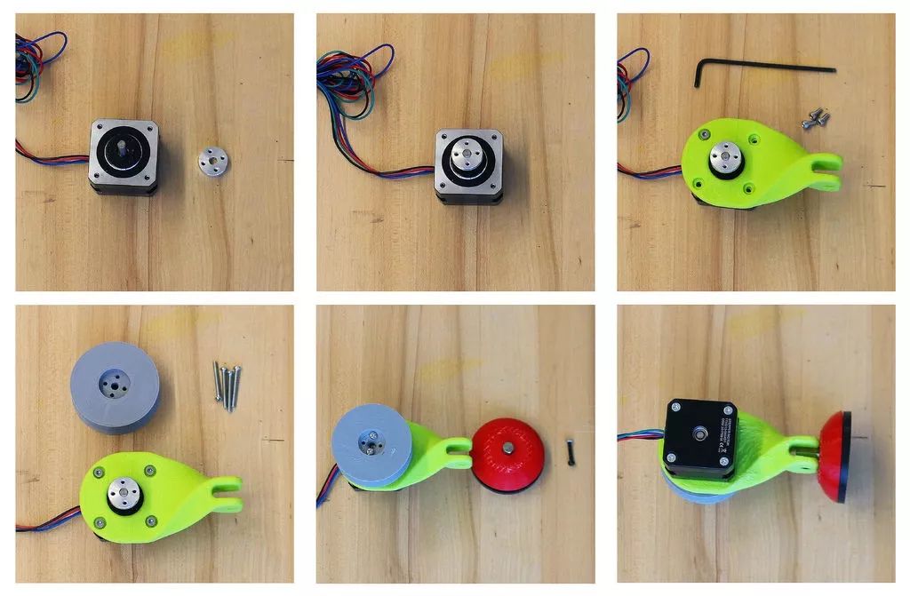
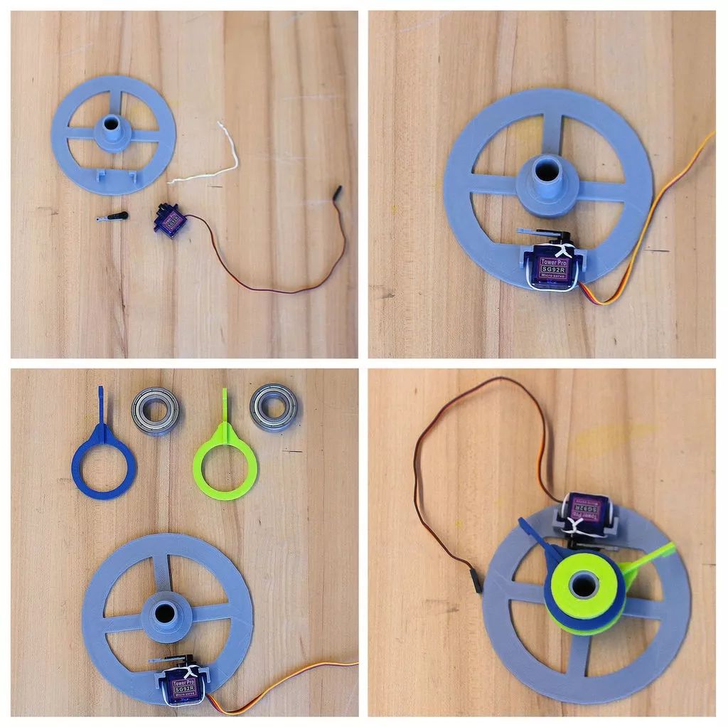
Parts that need to be 3D printed include: two motor mounts, two spools, and two suction cup domes with 1/8 inch holes, all materials printed in PLA.
Required hardware: two stepper motors, two suction cups, two universal mounting wheel axles, two bolts (#8-32 x 5/8 inch), eight spool screws (#4-40 x 1/2 inch), eight motor screws (M3 50 x 6mm motor screws) and several fishing lines.
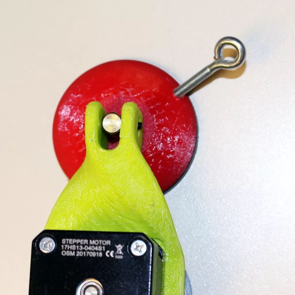
Note: The suction cup requires a long metal rod connected to the motor base.
1. Connect the stepper motor using a universal aluminum mounting axle. Use the screws that come with the mounting hub to install the hub near the end of the stepper shaft.
2. Use four 3D printed M3 screws to connect the twist motor bracket to the stepper motor. The base of the twist motor has a recess for securing the motor.
3. Use 4-40 screws to connect the 3D printed spool to the mounting hub.
4. Install the suction cup base. First, disassemble the suction cup, keeping the rubber suction cup, spring, and metal rod. Drill a “hole” of 1/8 inch in the suction dome and screw in the bolt, or use a suction cup dome with a hole, placing the 3D printed dome on the rubber suction cup. Push the motor base down onto the suction cup to allow the screws to pass through the metal rod.
5. Make another identical bracket.
6. Wrap the fishing line around the spool.
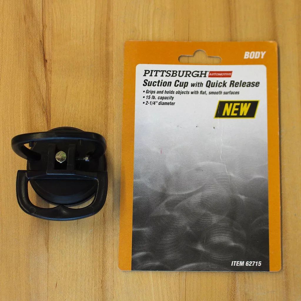
Note: Harbor Freight suction cups are a must as their metal rods are longer than others. Model number 62715.
Installation of the Pen Holder Gondola
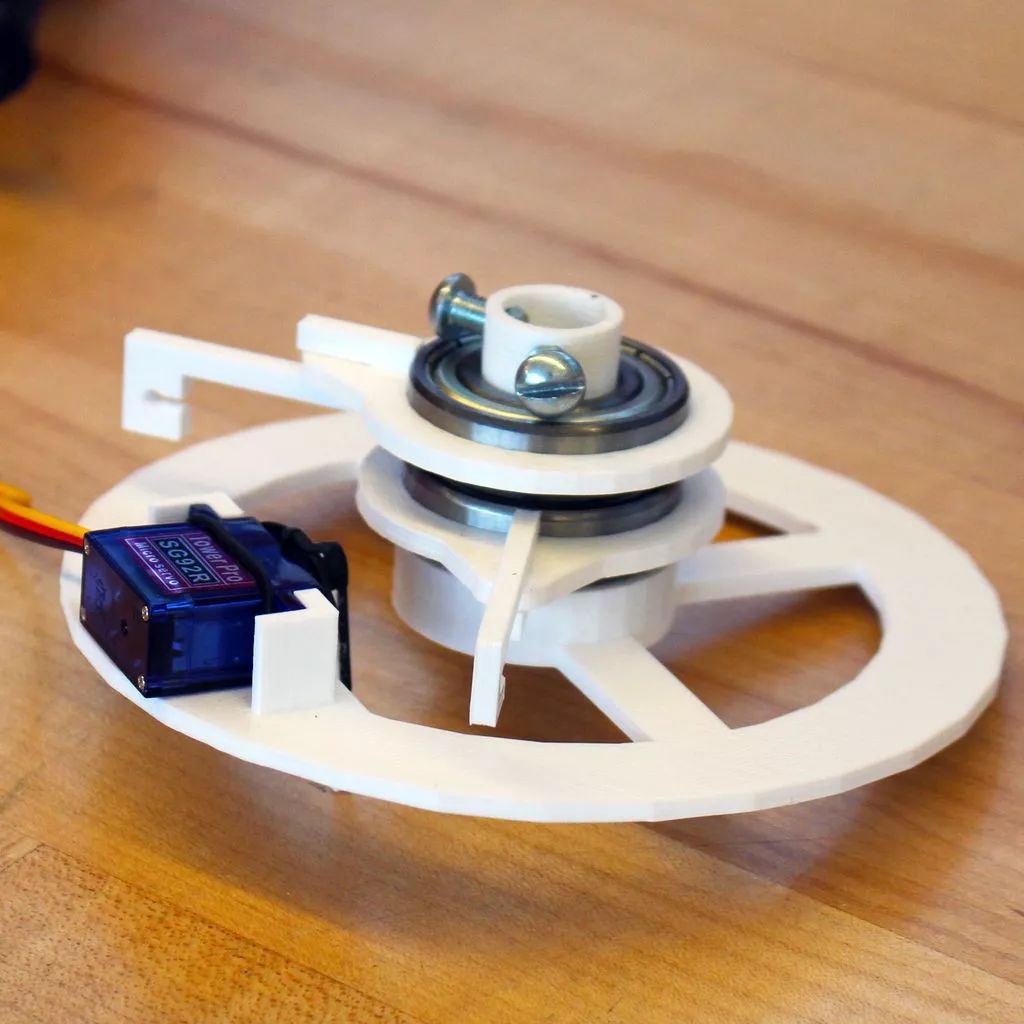
Parts that need to be 3D printed include: Polargraph Gondola, two bearing connecting arms, two bearing connectors, one gondola fixer, one motor extension board. Required hardware includes: one SG92R servo, two 6003zz bearings, and one zip tie.
1. Glue the 3D printed motor extension arm to one of the servo arms. In this step, you can use a paper clip to secure it, cutting it in half and gluing it to the servo arm.
2. Use a zip tie to secure the servo system to the gondola.
3. Connect the bearing connector with the bearing connecting arm. Push the bearings into the bearing connector assembly. The 3D printed parts need to be further polished to allow the bearings to slide into the bearing connector.
4. Slide the gondola with the bearing connector and arm. The axle on the 3D printed gondola also needs careful polishing to allow the bearings to slide down.
5. Install the gondola fixer, assemble everything together, and use screws to secure it to the gondola axle so that the pen can be fixed while moving.
Installing Software
Please use the Raspberry Pi preparation guide
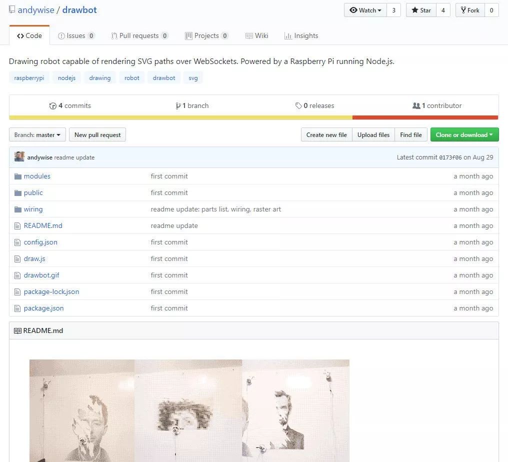
For this step, I recommend referring to the drawing robot GitHub. Update, upgrade the installation packages on the Raspberry Pi, and install other software:
Update and upgrade:
sudo apt-get update
sudo apt-get upgrade
Install NPM and Git:
sudo apt-get install npm
sudo apt-get install git
Install Node.js:
sudo npm install -g n
sudo n stable
Upgrade NPM – and remove the old apt-get version:
sudo npm install npm@latest -g
sudo apt-get remove npm
sudo reboot
Install pigpio C library:
sudo apt-get install pigpio *if you're using Raspbian Lite*
npm install pigpio
Install drawing robot software:
git clone https://github.com/andywise/drawbot.git
cd drawbot
npm i
Start the drawing robot software:
cd /drawbot
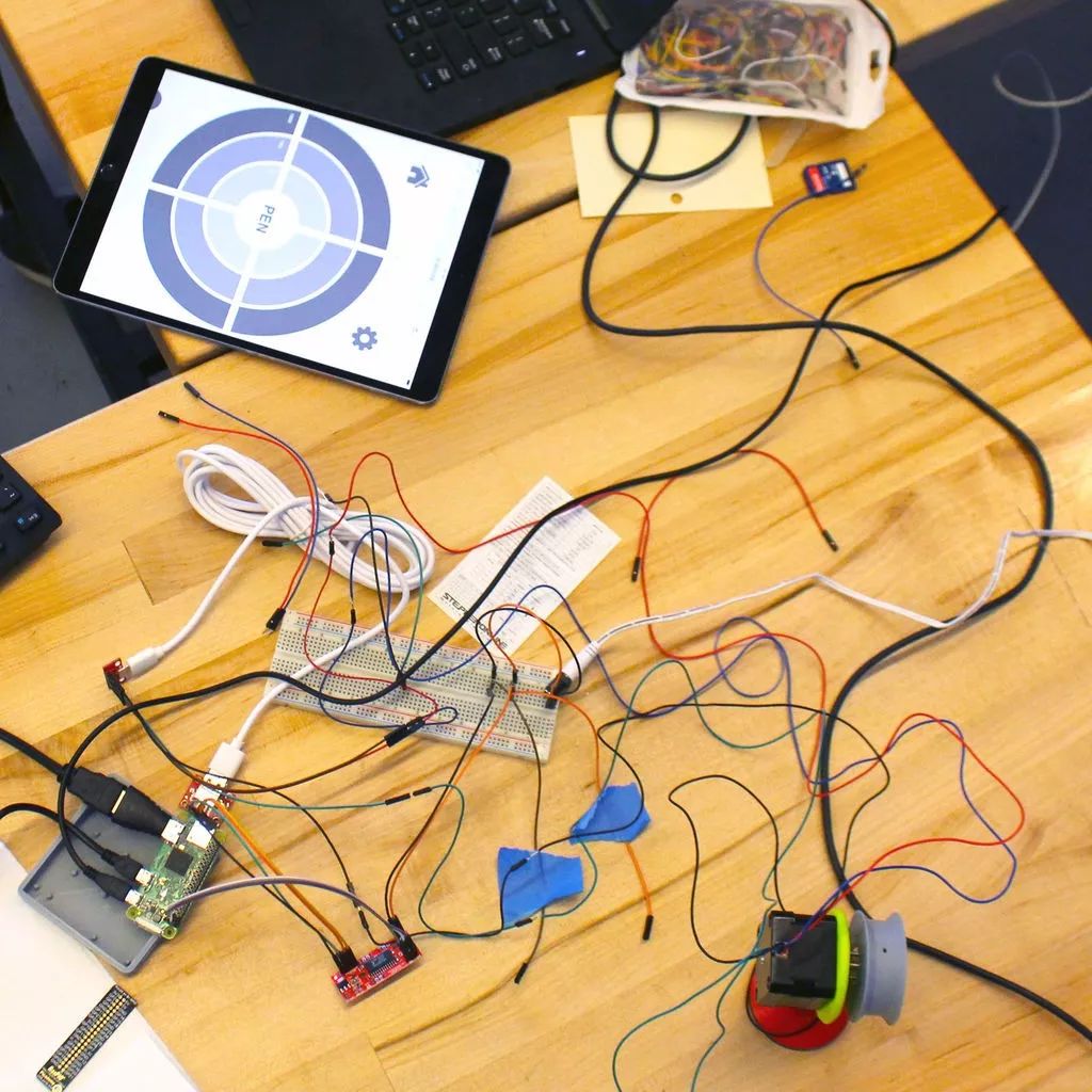
npm start -or- sudo node draw.jsConnect to the drawing robot control interface
Use another computer or access the robot control interface directly on the Raspberry Pi as follows:
Mac: Open http://raspberrypi.local/control to access the drawing robot control interface.
PC: Enter the Raspberry Pi’s IP address/control, e.g., http://10.167.5.58/control Raspberry Pi local: Open a browser. Access http://127.0.0.1/control.
Wiring
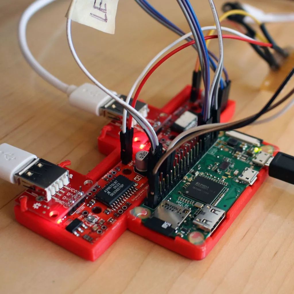
Required hardware includes: two USB A female adapter boards, two EasyDriver stepper motor driver boards, one Raspberry Pi Zero or other Raspberry Pi that supports WiFi, two stepper motors, two Micro USB adapter boards, and one 2.1mm x 5.5mm socket.
Other parts you might need: breadboard header pins for testing connections, 3D printed stepper motor and Raspberry Pi base circuit boards
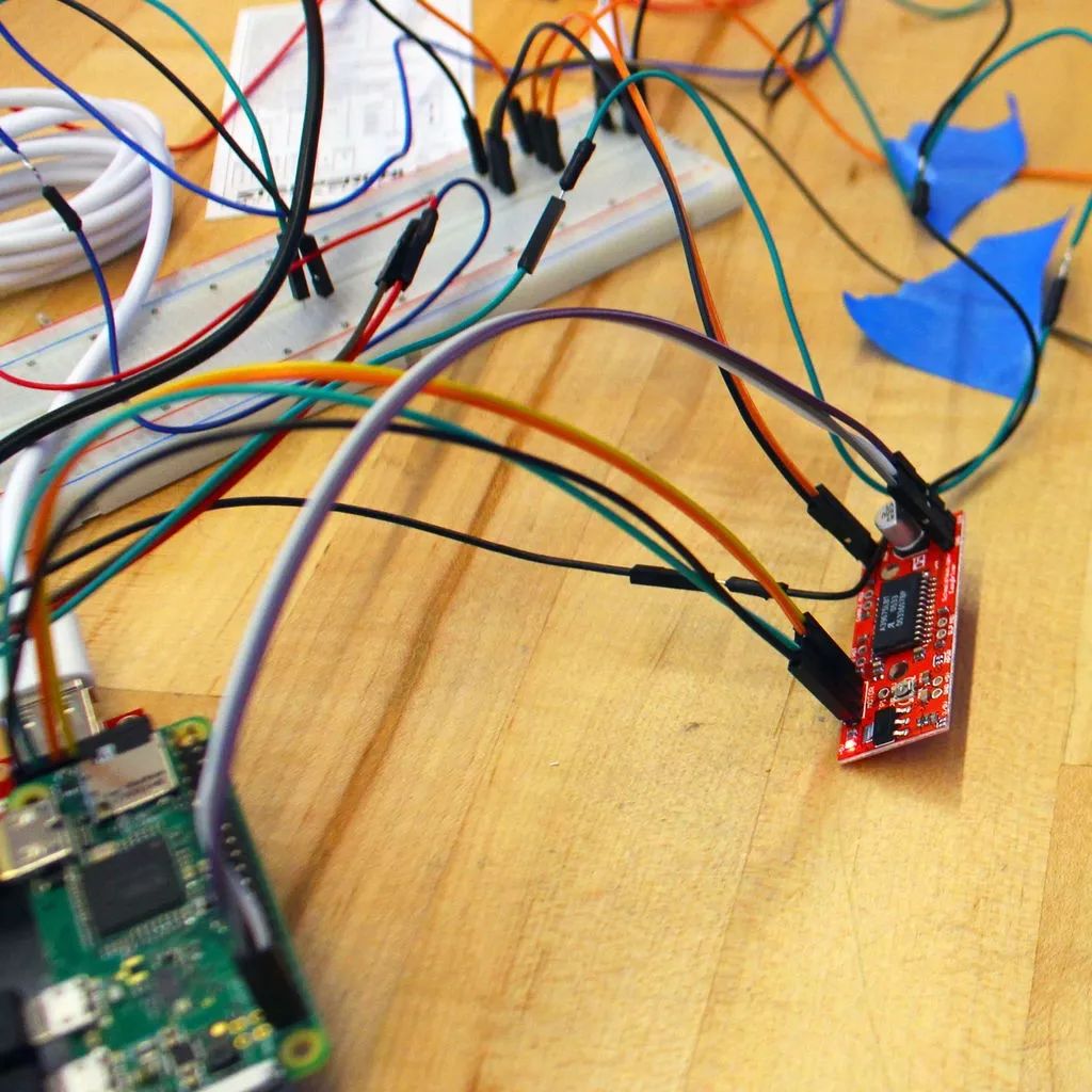
Connect the EasyDriver motor driver board to the Raspberry Pi:
Left driver: GND → Raspberry Pi GPIO 39, DIR → Raspberry Pi GPIO 38 (BCM 20), STE → Raspberry Pi GPIO 40 (BCM 21)
Right driver: GND → Raspberry Pi GPIO 34, DIR → Raspberry Pi GPIO 31 (BCM 6), STE → Raspberry Pi GPIO 33 (BCM 13)
Gondola motor: GND → Raspberry Pi GPIO 14, VCC → Raspberry Pi GPIO 1 (3V3 power), CNT → Raspberry Pi GPIO 12 (BCM 18)
Note: Perform tests to ensure connections are correct; it is recommended to connect the breadboard first before connecting other components.
1. Please solder the Raspberry Pi/EasyDriver header pins properly.
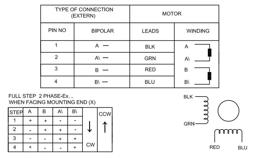
2. Connect each EasyDriver driver board interface on the circuit board to the USB female header. For this step, it is best to refer to the data sheet or parameters for the stepper motor. Ensure the windings/coil are kept together. The stepper motor has a pair of black, green, red, and blue wires.
Here, keep “Winding A” grounded, D + connected to the USB interface, and “Winding B” connected to VCC and D- on the USB interface.
3. Use jumper wires to connect the motors to the Raspberry Pi’s GPIO. Please refer to the above information.
4. Use jumper wires to connect the EasyDriver driver board to the Raspberry Pi’s GPIO. Please refer to the above information.
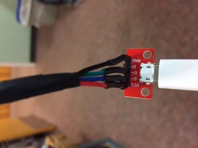
5. Reconnect the stepper motor wires to the Micro USB adapter board, ensuring all wires match correctly.
6. EasyDrivers need power. Connect the tip of the socket to “PWR IN” on the EasyDrivers, and connect the sleeve of the socket to the “GND” on the EasyDrivers. Use the circuit board to separate the power and ground from the socket to the EasyDriver driver board.
Testing the Drawing
Once your Raspberry Pi, EasyDrivers driver board, and USB adapter board are connected through the breadboard, you can proceed with testing.
1. Raspberry Pi Software Setup
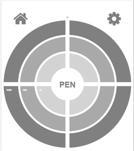
Start the drawing robot controller software on the Raspberry Pi. This makes it easier to control the motors and servos. Click the button in the center of the controller target to move the servo arm 90°, which facilitates testing and ensures the servo arm is correctly positioned, and can lift the pen off the surface.
Once you connect the Raspberry Pi and the drawing robot controller software, you will know.
2. Connecting the Stepper Motors
Starting one stepper motor at a time will make it easier to operate. Synchronize the stepper motor with the coordinates on the drawing robot controller target. The stepper motor must move smoothly. If the stepper motor wiring is correct and matches, then the stepper motor test is complete; proceed to test another.
After disconnecting the stepper motor power, find a flat, smooth surface to mount the stepper motor, ensuring they maintain a level plane with each other. Extend some fishing line from each spool and connect it to the support arm of the gondola.
Reconnect the stepper motor. Use the drawing robot controller to move the gondola. When clicking the upper right corner of the target, if the configuration file is not adjusted, the gondola should move to the upper right corner. If the gondola moves in the opposite direction, the mirrored file on the Raspberry Pi should be opened.
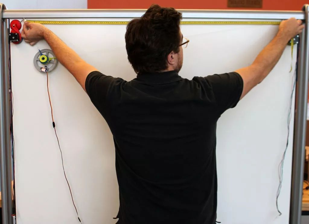
3. Measurement
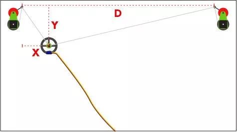
Next comes the measurement. We use a small retractable tape measure, all measurements are in millimeters. Click and set the values needed in the drawing robot controller, “D”, “X”, and “Y”. Instructions on how to measure.
As shown in the figure. The first “D” value is the distance between the spools. The next value is the starting position of the gondola. The “X” value is the measurement from the left spool to the position of the pen in the gondola. The “Y” value is the distance from the spool to the gondola. Enter these values into the settings of the drawing robot software. It is recommended to set the homepage in the upper left corner.
4. Drawing
Finally, we can start drawing!
As long as everything is measured as accurately as possible; the pen in the gondola is lifted off the surface and returned to position, the drawing robot can execute an SVG. Just drag a single path SVG onto the drawing robot software’s target to start drawing. I have added a calibration function for the drawing robot.
The drawing robot calibration file can be downloaded from the project repository. http://maker.quwj.com/project/80
via instructables.com/id/Drawbot
The links in the article can be clicked at the end to read the original text.

More Exciting Content
UltraV: Portable UV Index Meter
Create a Decent NAS with Raspberry Pi
Create a Toilet Condition Monitor with Raspberry Pi
Create an Automatic Irrigation System with Raspberry Pi
DIY a Wi-Fi Remote-Controlled Boat with ESP32 Development Board
DIY a Popular Gear: Flame Throwing Gauntlet
Make a Fantastical “Endless Extension” Mirror