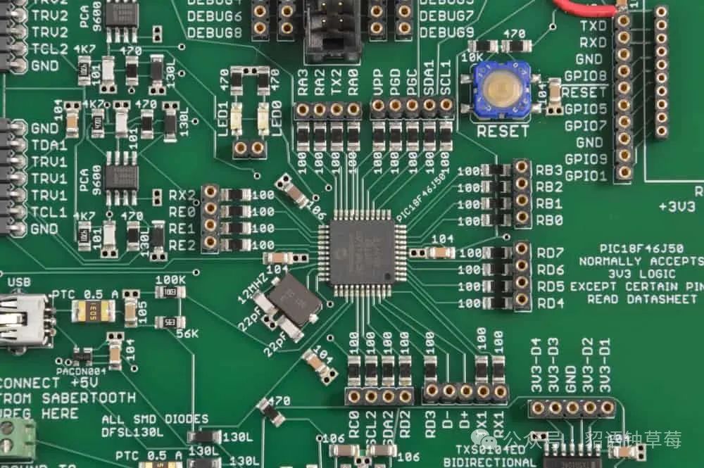
In modern industrial control systems, the reliability of PCBs directly affects the stability and lifespan of the entire system. Industrial environments often face harsh conditions such as high temperatures, high humidity, vibration, and electromagnetic interference, which impose strict requirements on PCB design. This article will explore high reliability design methods for PCBs in industrial control systems.Substrate Selection and Layer DesignIndustrial-grade PCBs should use high Tg (glass transition temperature) substrates, such as FR-4 high Tg materials (Tg>170°C) or polyimide substrates, to ensure good mechanical strength and insulation properties in high-temperature environments. In terms of layer design, a symmetrical structure should be adopted to avoid warping due to temperature changes. For multilayer boards, it is recommended to set a complete ground plane between critical signal layers to enhance EMI resistance. High-speed signal routing should consider impedance matching, controlling the characteristic impedance within a tolerance range of ±10%.Thermal Management StrategiesThermal management of industrial control PCBs is crucial. High-power devices should be equipped with sufficient copper foil heat dissipation areas, and buried copper technology should be used to increase heat conduction paths when necessary. Heat-sensitive components should be laid out away from heat sources and airflow direction should be considered. For areas with high current density, thicker copper (2oz or higher) should be used to reduce heat accumulation. Thermal via arrays can be designed to enhance heat dissipation efficiency, ensuring that the junction temperature (Tj) of critical components does not exceed 70% of the rated value.Moisture and Corrosion Protection DesignFor high humidity environments, a solder mask should cover all non-solder copper areas, and a conformal coating (moisture-proof, mildew-proof, salt mist-proof) should be applied to the entire board. Appropriate surface treatment processes, such as ENIG (Electroless Nickel Immersion Gold) or OSP (Organic Solderability Preservative), should be selected to enhance long-term storage stability. Redundant designs, such as parallel vias and backup connection paths, should be considered for critical interconnection areas to prevent single-point failures.EMC and Anti-Interference DesignElectromagnetic interference in industrial environments is severe, and strict EMC design should be implemented. Key measures include:Adopting a multi-point grounding strategy to maintain ground impedance <10mΩAchieving PDN (Power Distribution Network) impedance <0.5Ω (up to 100MHz) Separating digital and analog circuits with a “star” grounding schemeImplementing differential routing for critical signal lines, controlling inter-line coupling <-40dBUsing ferrite beads and common mode inductors to suppress conducted interferenceDesigning TVS protection circuits and filtering networks at I/O interfacesHigh Reliability Connector and Soldering DesignConnection reliability is key in industrial control systems. Industrial-grade high-reliability connectors, such as M12 connectors with locking mechanisms or heavy-duty connectors, should be used. PCB pad designs should follow IPC-7351B standards to ensure sufficient solder volume. For high current paths, pad area should be increased and through-hole technology should be considered to enhance mechanical strength.Testability DesignTestability directly affects product maintenance and production yield. Test point networks should be introduced in the design, following the IEEE 1149.1 JTAG standard to achieve boundary scan testing capabilities. Test pads should be reserved for critical nodes, ensuring that test point density meets flying probe test requirements. Built-in self-test (BIST) functions should be considered to support system-level diagnostics.Fault Redundancy DesignIndustrial control systems often require high MTBF (Mean Time Between Failures). Fault redundancy designs should be implemented, such as N+1 redundancy configurations for critical power supplies and dual-machine hot backup architectures for core processing units. Lightning protection circuits should be designed, including multi-stage surge suppression devices and common mode suppression networks, to ensure the system can withstand surge tests as specified by IEC 61000-4-5.ConclusionThe high reliability design of PCBs in industrial control systems is a systematic engineering task that requires comprehensive consideration of material selection, layout routing, thermal management, EMC design, and more. The design methods outlined above not only enhance the PCB’s tolerance in harsh environments but also extend the overall lifespan of the control system, reduce maintenance costs, and ensure the continuity and safety of industrial production.