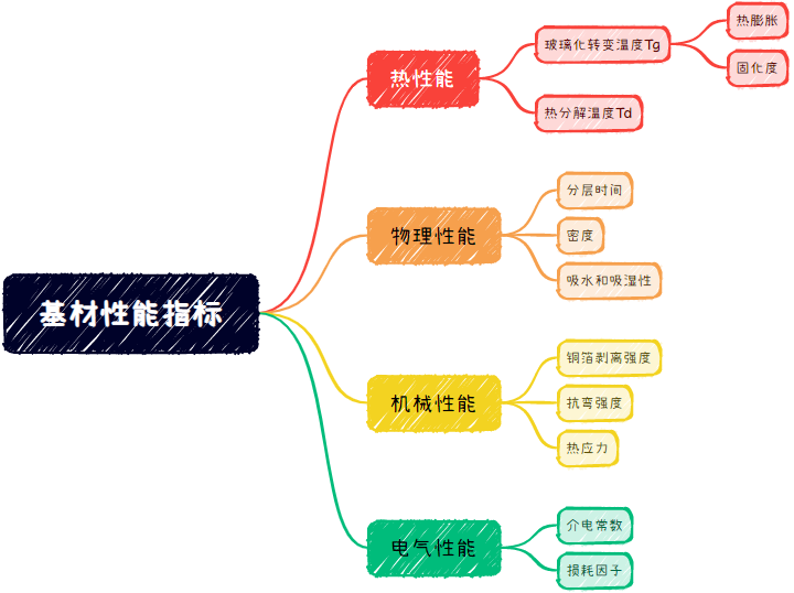
1. Key Performance Indicators
Physical Performance: Peel Strength / Coefficient of Thermal Expansion / Peel Strength
Chemical Performance: Tg / Td / Z-CTE
Electrical Performance: Dielectric Constant / Dielectric Loss / Flame Retardancy
Environmental Performance: Water Absorption / CAF Resistance / CTI
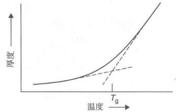
2. Glass Transition Temperature Tg
The glass transition temperature Tg is an important characteristic parameter of PCB materials, indicating the temperature at which the material transitions from a glassy state to a rubbery state. When the temperature is below Tg, the PCB material is in a rigid glassy state; when the temperature exceeds Tg, the material becomes soft and pliable, exhibiting reversible deformation properties.
The glass transition temperature Tg significantly affects the performance of PCB materials, influencing their thermal deformation characteristics, mechanical strength, and electrical performance. Therefore, during the design and manufacturing of PCBs, it is essential to select appropriate materials and Tg temperatures based on the application environment and requirements. For instance, if the application environment temperature is high, requiring the PCB to have good thermal stability and mechanical strength, a PCB material with a higher Tg temperature should be selected.
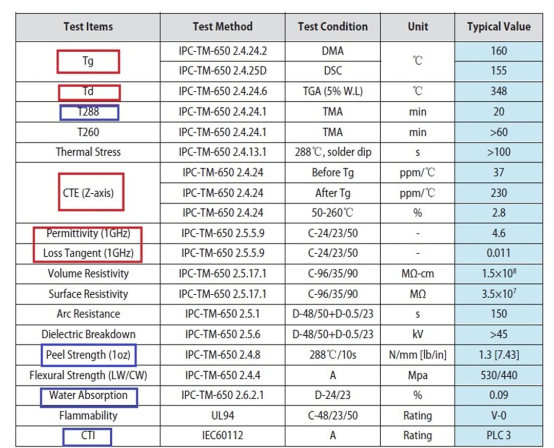
Tg temperature is typically measured using Dynamic Mechanical Analysis (DMA) or Differential Scanning Calorimetry (DSC). These testing methods can quantify the thermal performance of PCB materials at different temperatures to determine their glass transition temperature.
High Tg value substrates tend to be more rigid and brittle than low Tg value substrates. Lower copper peel strength values and shorter delamination test times are also associated with high Tg values.
High-end FR4 resin systems often possess high Tg and high Td values.
IPC Standard Classification:
Impact on PCB Use: Tg affects the Z-CTE of the material, high-temperature deformation, dimensional stability, and other properties.
3. Coefficient of Thermal Expansion
The coefficient of thermal expansion (CTE) of a PCB is an important parameter that measures the dimensional stability of materials during temperature changes. The thermal expansion coefficient is divided into X-axis, Y-axis, and Z-axis thermal expansion coefficients, generally referring to the Z-axis expansion coefficient, as it has the greatest impact on material reliability. Specifically, CTE describes the ratio of the change in length of the material to its original length for a unit temperature change. For PCB materials, linear thermal expansion coefficients are typically used to measure their linear changes in size during temperature variations.
The thermal expansion coefficient of PCB significantly affects its performance and reliability. The lower the CTE value, the better the dimensional stability of the material; conversely, the higher the CTE, the worse the stability. In the manufacturing process of electronic devices, components that meet performance requirements must be soldered (installed) to the printed circuit board using appropriate methods to form a circuit board assembly with specific functions. Since the components and substrates are made of different materials, each having different thermal expansion coefficients, the impact of thermal expansion needs to be assessed by comprehensively considering the actual conditions of the materials and components in different directions.
To ensure the performance and reliability of electronic devices, the CTE of PCBs must be analyzed and evaluated. When selecting PCB materials, their thermal expansion coefficients must be matched with the application environment and requirements. For example, in applications requiring high dimensional stability, PCB materials with lower CTE values should be chosen.
4. Thermal Decomposition Temperature Td
The thermal decomposition temperature Td refers to the temperature at which PCB materials begin to decompose at high temperatures. This is also one of the important parameters for formulating PCB thermal replacement processes.
The thermal decomposition temperature of PCB materials affects their stability and lifespan at operating temperatures. If the thermal decomposition temperature of PCB materials is low, they are prone to decomposition and oxidation at high temperatures, leading to degradation and failure of material performance. Therefore, when selecting PCB materials, their thermal decomposition temperature must be considered to ensure stability and lifespan at operating temperatures.
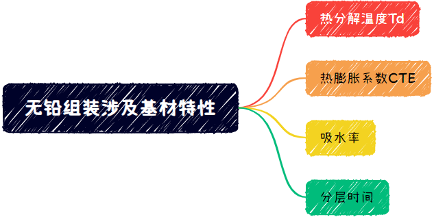
Generally speaking, the thermal decomposition temperature of traditional PCBs is around 300°C, while lead-free materials require higher thermal decomposition temperatures, typically above 340°C. Therefore, when formulating PCB thermal replacement processes, appropriate heating temperatures and times must be selected according to the different requirements of materials to ensure that materials do not decompose or oxidize during heating.
With the advent of lead-free processes, substrate selection must consider not only the glass transition temperature but also the thermal decomposition temperature. Resins begin to decompose at specific temperature points, where chemical bonds within the resin start to break, resulting in volatile components escaping and a reduction in mass.
Td is typically defined as the temperature point corresponding to a 5% loss of the original mass during decomposition.
5. Copper Foil Peel Strength
Peel strength measures the bonding strength between the conductor and the substrate material. The thickness of the copper foil affects the peel strength test values, with a default thickness of 1oz copper.
Copper foil peel strength is one of the important indicators for evaluating PCB quality. Peel strength testing generally refers to the bonding strength test between copper foil and substrate or between copper foil and brown film. A universal tensile testing machine is used to vertically stretch the copper foil at a certain rate, detecting the force value when the copper foil peels from the substrate, and calculating its peel strength.
The purpose of peel strength testing is to assess the bonding strength between PCB copper foil and substrate under receiving conditions, thermal stress, high-temperature conditions, and other pre-treatment states. Different standards have different requirements for copper foil peel strength; for example, IPC-TM-650 2.4.8 standard requires a copper foil peel length of over 28mm and a peel strength of over 1.4N/cm, while GB/T 13542.2-2009 standard requires a copper foil peel length of over 12.7mm and a peel strength of over 0.5N/cm.
In practical applications, peel strength testing can help manufacturers understand product quality and reliability, providing feedback for product improvement and optimization. Meanwhile, PCB designers and engineers need to fully understand the various factors affecting copper foil peel strength and take corresponding measures during the design and manufacturing processes to ensure product quality and reliability.
6. Water Absorption and Moisture Absorption
The ability of materials to resist water absorption in the air or when immersed in water. Moisture can easily expand and diffuse, leading to delamination of the substrate. Moisture also affects the conductive anodic filament (CAF) growth ability of the substrate.
Water absorption and moisture absorption are important indicators that need attention, as they directly affect the performance and stability of PCBs. Here are some key points regarding PCB water absorption and moisture absorption:
Influencing Factors: The water absorption and moisture absorption of PCBs are mainly influenced by their material composition and manufacturing processes. For instance, some PCB materials may contain hydrophilic groups or porous structures, which can increase the water absorption and moisture absorption of PCBs.
Performance Impact: When PCBs absorb moisture, key performance parameters such as dielectric constant and coefficient of thermal expansion may change. These changes can lead to signal transmission delays or distortions, affecting the performance of the entire electronic device.
Reliability Issues: PCBs exposed to high humidity environments for extended periods may absorb moisture, leading to dimensional changes, warping, or cracking. These issues can affect the installation accuracy of electronic components and may cause circuit failures, reducing the reliability of electronic devices.
Protective Measures: To reduce PCB water absorption and moisture absorption, several protective measures can be taken. For example, applying waterproof coatings on the PCB surface or using materials with low moisture absorption. Additionally, during the design and manufacturing processes, the application environment and humidity conditions of the PCB should be fully considered to select appropriate materials and processes.
The flame retardancy of PCBs is an important performance indicator used to evaluate the burning characteristics of materials after ignition. Depending on the flame retardancy, PCBs can be classified into three levels: V-0, V-1, and V-2.
The testing and evaluation of flame retardancy are usually conducted according to international standard UL94 and domestic standard GB/T 2408. In the tests, specialized flame retardancy testing instruments are used for ignition tests and vertical burning tests on PCBs. The ignition test is used to determine the self-ignition performance of the material, while the vertical burning test assesses the extent of flame spread. Through a rigorous testing process and accurate testing data, reliable flame retardancy evaluation reports can be provided.
Flame-retardant PCBs are materials with good flame retardancy, made from E-grade insulating materials, with a glass transition temperature of 150°C. This material achieves UL94 V-0 flame retardancy level, with good insulation, light transmittance, and heat resistance. Flame-retardant PCBs can also achieve halogen-free flame retardancy, meeting the strictest environmental requirements of globally renowned companies. Additionally, anti-static grade flame-retardant PCBs are also materials with excellent flame retardancy, achieving V-0 flame retardancy level, with good formability, excellent mechanical properties, high dimensional stability, and high flame retardancy level.
8. Dielectric Constant
The dielectric constant of resin is smaller than that of glass cloth; as the resin content increases, the dielectric constant decreases.
The dielectric constant is an important parameter for measuring the electrical performance of insulating materials, specifically indicating the relative permittivity of the insulating material filling the capacitor plates. The higher the dielectric constant, the better the insulation performance.
For PCB substrates, the dielectric constant is a very important parameter, as the speed and integrity of signal transmission on the PCB are influenced by the dielectric constant. Generally, the higher the dielectric constant, the slower the signal transmission speed. Therefore, when selecting PCB substrates, the impact of dielectric constant must be considered based on actual needs.
Moreover, the dielectric constant is also affected by factors such as temperature and humidity. Therefore, in practical applications, these factors must be fully considered to ensure the performance and reliability of electronic devices.
9. Loss Factor
The loss factor (also known as loss tangent or tangent of the loss angle) is a parameter that describes the energy loss of a material under the influence of an electric field. The larger the loss factor, the higher the energy loss of the material under the influence of the electric field.
The loss factor of PCBs is mainly affected by the dielectric constant, conductivity, frequency, and temperature of the material. In high-frequency applications, the loss factor of PCBs will significantly increase, leading to signal attenuation and distortion. Therefore, in high-frequency circuit design, PCB materials with low loss factors should be selected to ensure signal integrity and stability.
Additionally, the manufacturing process of PCBs also affects the loss factor. For instance, surface treatment, lamination processes, and copper foil thickness can all impact the loss factor. Therefore, in practical applications, suitable PCB materials and process parameters should be selected based on specific application requirements and manufacturing process requirements to reduce the loss factor and improve circuit performance and reliability.
The loss factor of resin is larger than that of glass cloth; as the resin content increases, the loss factor increases.
The dielectric constant generally decreases with increasing frequency, while the loss factor generally increases with increasing frequency, but will reach a maximum at a certain frequency point.
The dielectric constant and loss factor typically increase with rising water absorption rates.
In addition to the aforementioned substrate performance indicators, there is also the IPC-410 series standards, IPC-4101 rigid and multilayer printed board substrate specifications, IPC-4103 high-speed/high-frequency application substrate specifications.
10. CAF Resistance
The CAF resistance of PCBs refers to their ability to resist ionic migration, especially in humid environments. CAF, or Conductive Anodic Filament, is an electrochemical reaction that occurs in humid environments, leading to the formation of conductive pathways between the anode and cathode in the circuit, which can cause short circuits.
Specifically, when PCBs are exposed to humid environments for extended periods, the internal materials may absorb moisture, increasing the moisture absorption of the substrate. In cases of increased substrate moisture absorption, what previously required 100,000 hours of insertion may now only require 10,000 hours to show a decline in insulation performance. This is particularly critical as the spacing between lines and holes continues to decrease, raising the requirements for insulating substrates. Therefore, to improve PCB CAF resistance, materials with low moisture absorption should be selected, and special surface treatments should be conducted.
11. Comparative Tracking Index (CTI)
The CTI of PCBs refers to the highest voltage value that solid insulating materials can withstand without forming leakage traces on their surface under the combined effects of an electric field and electrolyte, measured in volts. The CTI testing device consists of a voltage supply device, two platinum electrodes with a cross-section of 2mmX5mm, one end of the electrodes cut at a 30° angle, and a droplet needle for adding electrolyte. The sample thickness should be no less than 3mm, and the area should be no less than 15mmX15mm square. The electrolyte used is ammonium chloride aqueous solution or sodium alkyl naphthalene sulfonic acid solution. A low voltage is then applied to the two electrodes, with the droplet needle dispensing a drop of approximately 20mm³ of electrolyte every 30 seconds until leakage traces appear on the sample surface. The voltage is then increased, and the above steps are repeated to create a voltage versus droplet relationship curve. The CTI value is determined from the voltage corresponding to 50 drops of electrolyte on the curve.