The BYD Han, as BYD’s attempt to penetrate the mid-to-high-end market, has achieved cumulative sales of 110,000 units within a year of its launch, which is the most direct recognition of its success. Out of curiosity about the technology, let’s outline the interfaces of various controllers in the BYD Han. First, let’s take a look at the network diagram of the BYD Han to get a general understanding of the connections between the controllers, as shown in Figure 1. Combined with the introduction of the gateway controller’s interfaces (as shown in Figure 2), the green chassis network, comfort network, ADAS network, power network, and ECM network in Figure 1 all use the CAN bus, and the ECUs mounted on each network are also clear, summarized in Table 1.
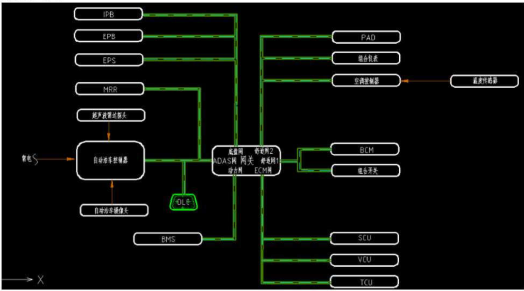
Figure 1: Network Architecture of BYD Han
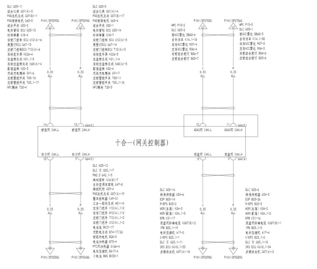
Figure 2: Interface Definition of the Gateway Controller
| Network Segment | Involved ECUs |
| Comfort Network | Instrument cluster, PAD host assembly, right door controller, ambient light ECU, rear display, main seat assembly, rear left seat assembly, left front window control, NFC, wireless charging module, etc. |
| Power Network | Shift panel, automatic air conditioning rear panel, vehicle controller, three-in-one powertrain, battery pack, battery heater, PTC air heater, small battery BMS, etc. |
| ADAS Network | Front ACC radar, automatic parking, right rear ACC radar, left rear ACC radar, right front combination lamp, left front combination lamp, etc. |
| Chassis Network | ESP, R-ESP, EPB, IPB, C-EPS, SRS, multimedia host, etc. |
Table 1: Summary of ECUs in Various Local Area Networks
Next, let’s select a few ECUs to take a closer look.
01
Automatic Parking Assist System
Similar to most parking systems on the market today, the BYD Han features automatic parking in, horizontal parking out, and self-selected parking spaces. In automatic parking mode, the system automatically searches for available parking spaces on the left and right using ultrasonic sensors and a panoramic camera mounted on the vehicle’s side.
In self-selected parking space mode, the driver selects a suitable parking space within the system’s detection range. Once the parking space is selected, initiating parking will enter parking mode.
In horizontal parking out mode, the driver confirms the parking direction by signaling, after which the system takes over vehicle control.
The circuit diagram of the automatic parking assist system is shown in Figure 3. The interface of the IPA module is shown in Figure 4.
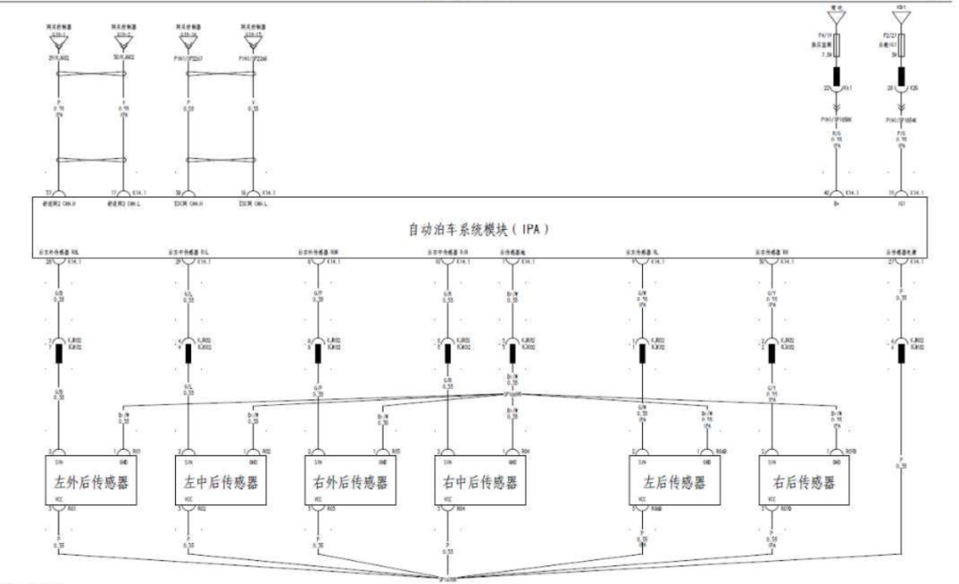
Figure 3: Circuit Diagram of the Automatic Parking Assist System
The definitions of each pin in the connector are shown in Figure 4.
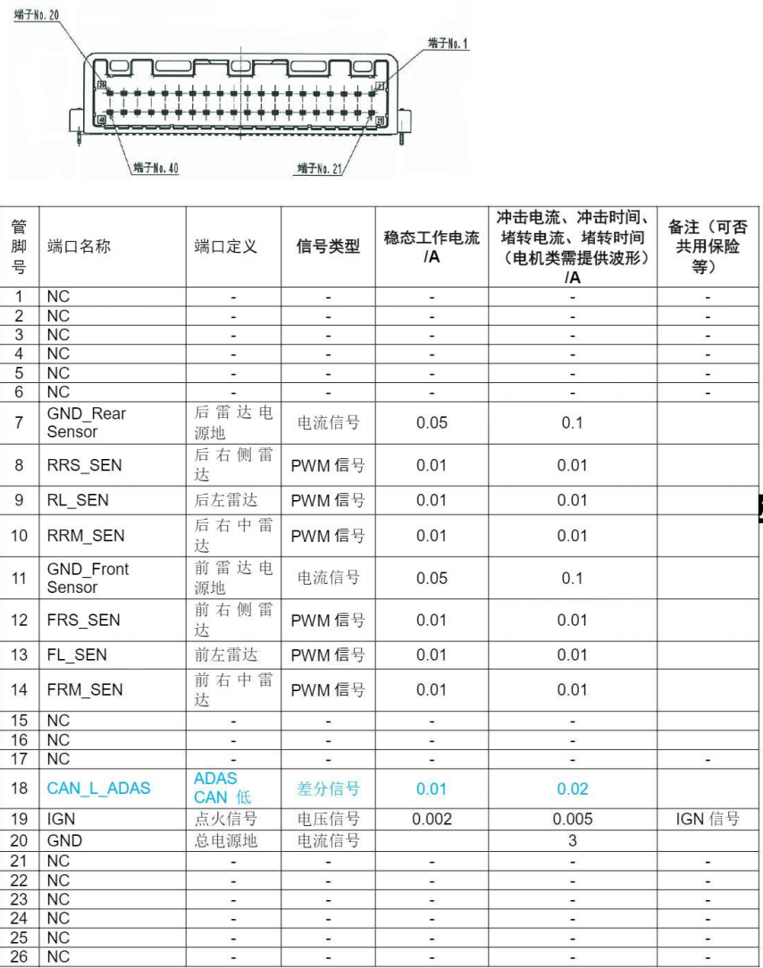
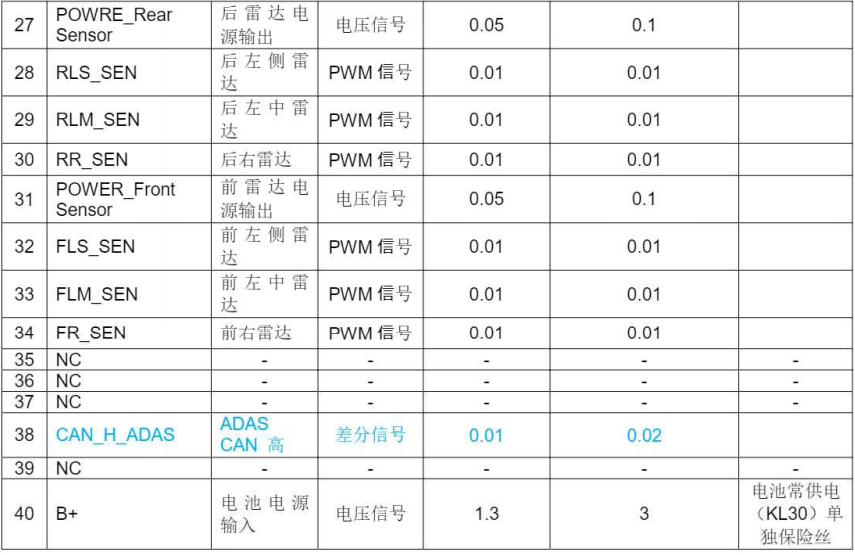
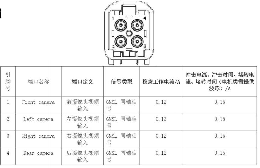
Figure 4: Interface Definition of the Automatic Parking Assist Controller
02
Vehicle Controller
As mentioned in the previous article about the vehicle power-up and power-down process, the Vehicle Controller (VCU) is one of the important controllers in the vehicle. It is responsible for coordinating various subsystems and managing the overall operational status of the vehicle. In addition to managing high-voltage power-up and power-down, it also calculates the required motor output torque and other parameters based on the driver’s operational intentions from the accelerator pedal, gear position, brake pedal, etc., as well as the power battery’s charge level, ensuring the vehicle operates normally. Additionally, it implements different levels of energy recovery based on the power battery’s charge level, battery temperature, and driving brake.
The VCU in the BYD Han is installed behind the driver’s area, as shown in Figure 5. The VCU is secured to the vehicle’s chassis with four hex flange bolts. It has only one external 64-pin connector, with the interface definition shown in Figure 6.
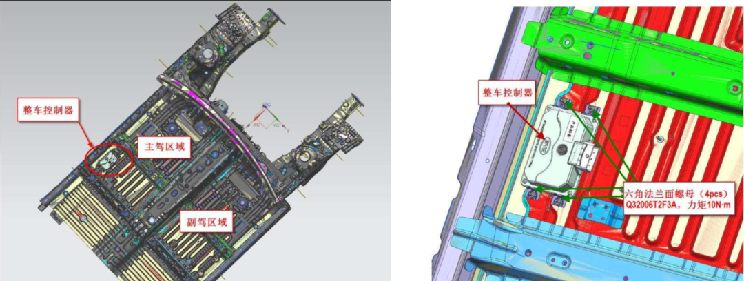
Figure 5: Installation Location of the Vehicle Controller
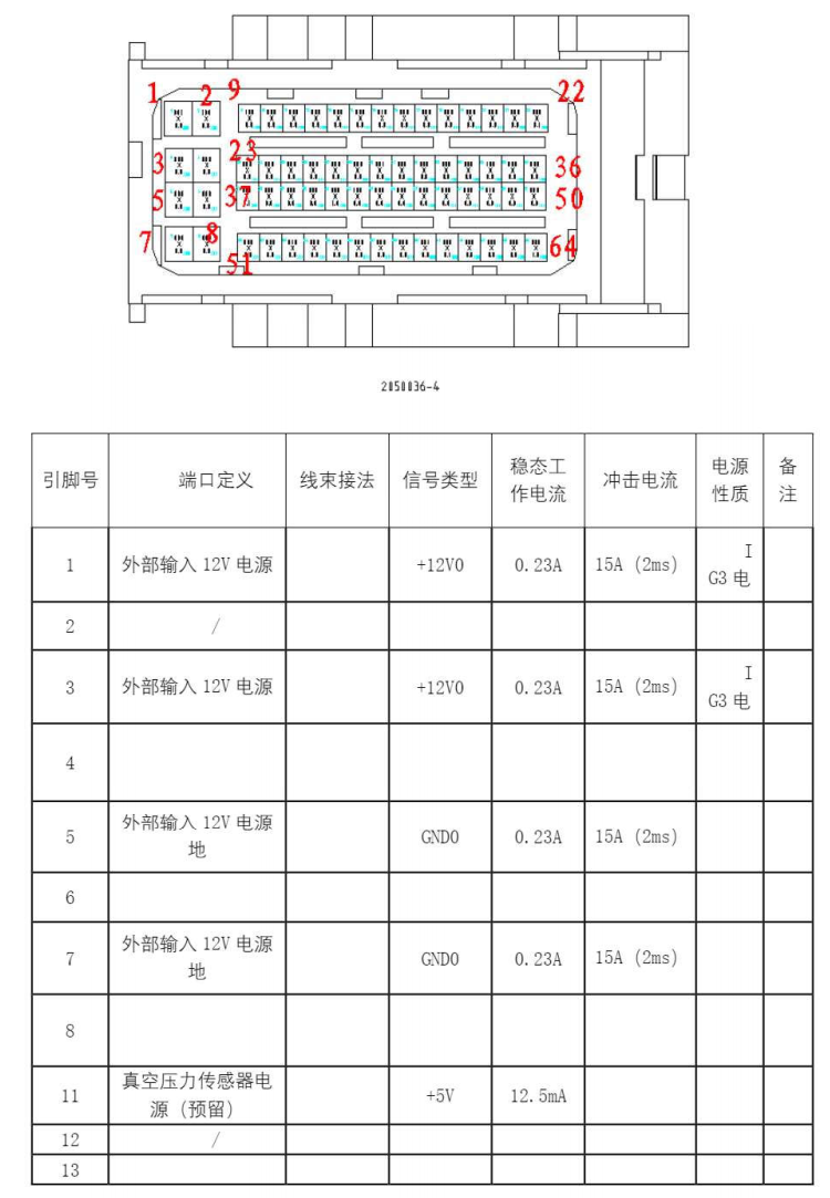
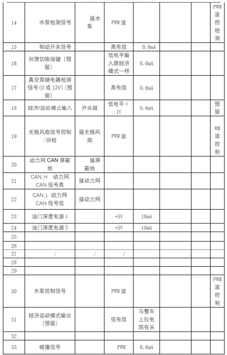
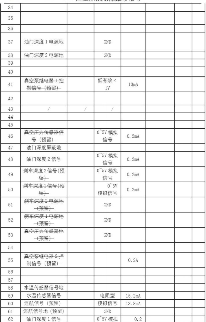
Figure 6: Interface Definition of the Vehicle Controller Connector
03
Conclusion
The above is a summary of information regarding two selected controllers. It can be seen that the current network architecture of the BYD Han is still relatively traditional and distributed, without extensive use of Ethernet and domain controllers. However, BYD recently released the E3.0 platform, which introduces four domain controllers and BYD OS, where the power domain integrates the VCU, BMS, Inverter, PDU, DCDC, and ACDC control components (this part is also done by Huawei, known as the seven-in-one controller), which is quite noteworthy. We look forward to BYD implementing it soon.
If you need information about the BYD Han, feel free to consult us.
Recommended Reading
Some Insights on ASPICE in Work
Guide for Automotive Functional Safety Engineers
Detailed Explanation of Bootloader Based on UDS
Understanding the Vehicle Power-Up and Power-Down Process
OEM: Six Experience Summaries for Collaborating with Software Suppliers
Understanding Vehicle Ethernet Switch VLAN
Detailed Explanation of AURIX TC3XX Series SOTA Mechanism
Comprehensive Overview of Audi e-tron Internal Systems | Download Attached
ID.3 and Volkswagen’s Electrification Platform | Download Attached
Comprehensive Overview of CAN Bus Error Frames | Download Attached
Introduction to DoIP Protocol, Material Sharing!
Detailed Explanation of Vehicle Network OTA System Development | Download Attached
Understanding Automotive Embedded AUTOSAR Architecture | Download Attached
Research on Tesla Autopilot System Safety | Download Attached
Sharing is not easy, please give a 【Like】