Overview: This article mainly discusses the basic principles of QSPI communication, an upgraded version of SPI communication. It aims to help readers understand and apply the QSPI data transmission method. This article is a sister piece to my previous article on SPI communication, which interested readers can refer to first: Fundamentals of C Language Applications – Implementing SPI Communication Using GPIO Simulation. All images and texts in this article are original works by the author, and copyright is reserved. Any piracy will be pursued!QSPI (Quad Serial Peripheral Interface) is an enhanced version of SPI, achieving high-speed data transmission through 4 data channels. At the same clock frequency, its transmission speed is 4 times that of SPI.1. Related Terminology
- SCLK: Clock signal generated by the master, controlling the rhythm of the entire transmission.
- D0: Data data0 signal. (When only using D0 to write cmd, it degenerates to SPI protocol)
- D1: Data data1 signal.
- D2: Data data2 signal.
- D3: Data data3 signal.
- CS: Chip Select signal. Like SPI’s SS/CS, it is active low.
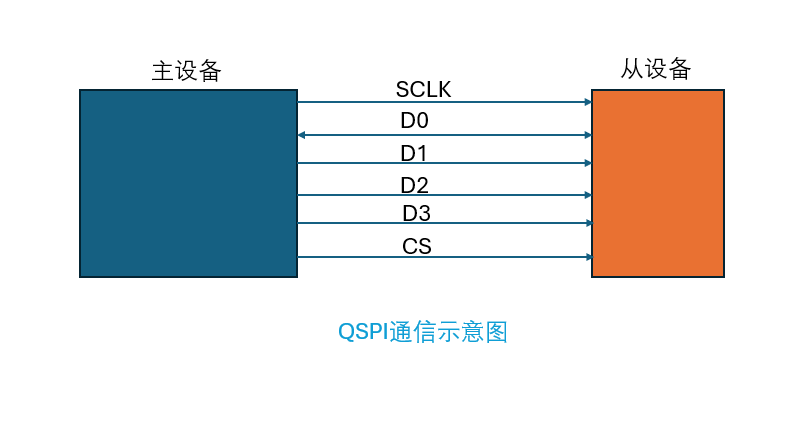
2. QSPI Data Transmission Diagram
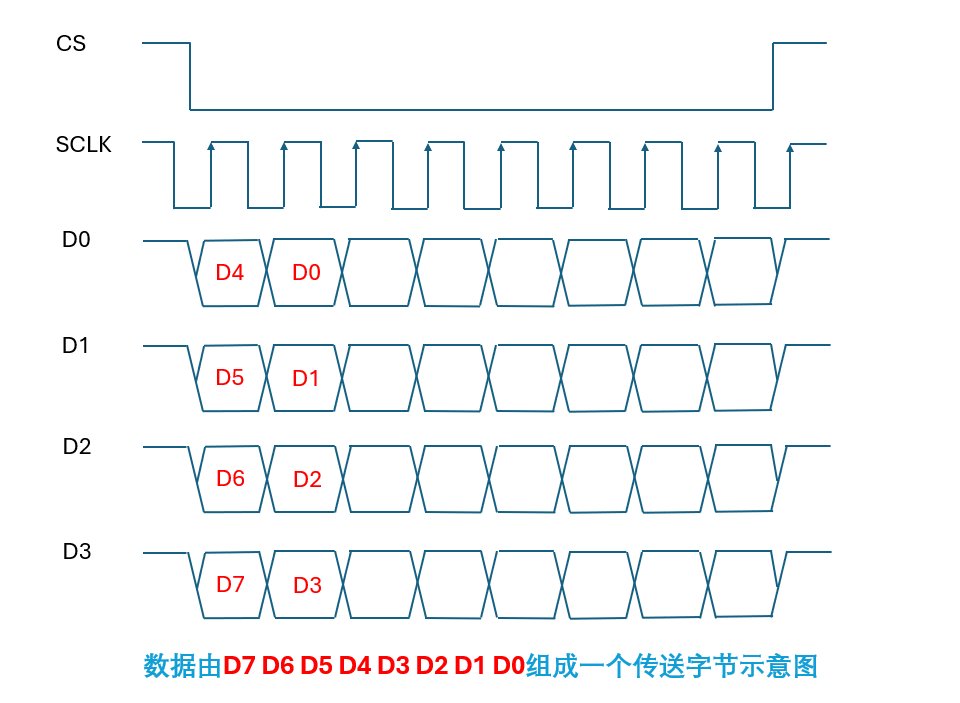
- As seen in the figure below: data is latched on the rising edge of the clock, while data transitions are only allowed during the low period of the clock. Two clocks can complete the transmission of one byte. A complete byte is composed of D0~D7, similarly, eight clocks can complete the transmission of 4 bytes. (Under the traditional SPI protocol, 8 clocks can only write one byte of transmission).
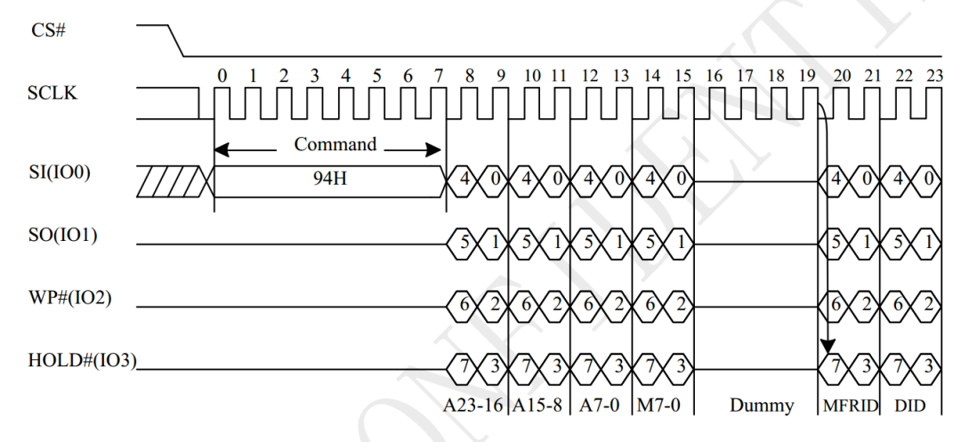
- The following figure is a waveform diagram of the SPI flash through the QUAD I/O Read Electronic Manufacturer & Device ID (QREMS) Sequence (Command 94).
 3. Implementing QSPI to Write One Byte Using C Language Simulation of GPIO
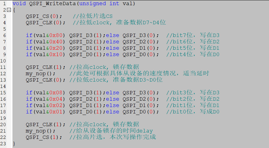
- Source Code
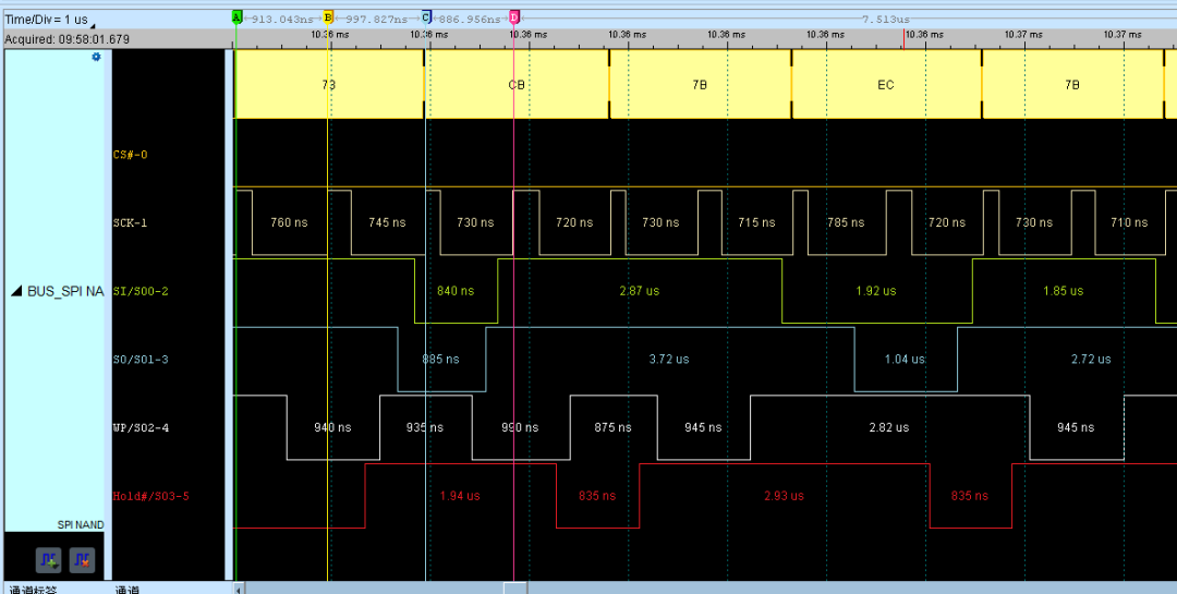
- The following is the actual waveform output generated by the above code. From the waveform, it can be seen that the first transmitted data is sampled at the rising edges of the first and second clocks, yielding 0111 0011 = 0x73. Similarly, the second transmitted data is sampled at the rising edges of the third and fourth clocks, yielding 1100 1011 = 0xCB; subsequent data can be inferred in the same manner.
 4. Core Application Areas of QSPI
- Embedded Microcontrollers (MCU): Used as a program storage interface, connecting NOR Flash/QSPI Flash to store firmware and boot code, compatible with mainstream MCUs like STM32, ESP32, PIC, etc.
- Programmable Logic Devices (FPGA/CPLD): Used for loading configuration programs or expanding external storage to meet high-speed data caching and firmware upgrade needs.
- Consumer Electronics: Devices such as smartwatches, Bluetooth headsets, and set-top boxes, used for storing system programs and multimedia data, balancing transmission speed and power consumption.
- Industrial Control: PLCs, industrial sensors, and data acquisition modules read configuration files and log data via QSPI, meeting the stability requirements of industrial environments.
- Automotive Electronics: In-vehicle navigation, dashboards, and vehicle systems connect to high-reliability flash memory to store map data and system programs, supporting high-speed startup and data updates.
- Internet of Things (IoT) Devices: Low-power IoT terminals (such as smart locks and environmental monitoring devices) use QSPI Flash to store firmware and sensor data, balancing low power consumption and transmission efficiency.
In conclusion:Compared to communication protocols like SPI, I2C, and UART, the main feature of QSPI is its high speed.The clock limit of the QSPI controller in most general-purpose MCUs is 133MHz, and the rated speed of conventional QSPI Flash is concentrated around 300~500Mbps. However, if PCB routing, impedance matching, and other designs are not optimized for high speed, it will limit the clock frequency, resulting in an actual speed range of 100~300Mbps. Additionally, protocol overhead (instruction and address transmission occupying part of the bandwidth) means the actual effective speed is about 80% of the base bandwidth, with actual communication speeds generally in the range of 50~100Mbps. Of course, this speed is already a significant leap compared to the ordinary I2C’s 100~400Kbps, which is quite impressive! ^-^Here are links to related articles by the author for interested readers to refer to.Fundamentals of C Language Applications – Implementing SPI Communication Using GPIO SimulationFundamentals of C Language Applications – I2C Bus Simulation ImplementationOriginal content is not easy to create, please follow, like, and share. Thank you!