1. Photointerrupter
1.1 Common Types of Photointerrupters
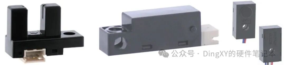
(1) Slotted Photointerrupter
This sensor has the emitter and detector positioned opposite each other, detecting objects that pass through the slot between the emitter and detector. There are various photoelectric sensors with different slot widths or depths depending on the detected object.
(2) Reflective Photointerrupter
This type of sensor operates on the principle that the detector detects the reflected light beam from an object.
(3) Separate Photointerrupter
The most unique feature of this sensor is that the emitter and detector are packaged independently. It achieves a longer detection range similar to a photoelectric sensor.
1.2 Description of Photointerrupter Trigger Logic
(1) Trigger States of Slotted and Separate Photointerrupters
① When light enters: Indicates that the beam is not obstructed, which is the untriggered state.
② When light is blocked: Indicates that the beam is obstructed, which is the triggered state.
(2) Trigger State of Reflective Photointerrupter
① When not detected: Indicates that the emitted beam has not been reflected back by an object, which is the untriggered state.
② When detected: Indicates that the emitted beam has been reflected back by an object, which is the triggered state.
(3) Description of Trigger Logic
① When the photointerrupter is in the triggered state, Vout is at a low level (L), indicating low-level triggering.
② When the photointerrupter is in the triggered state, Vout is at a high level (H), indicating high-level triggering.
1.3 Photointerrupter Response Time
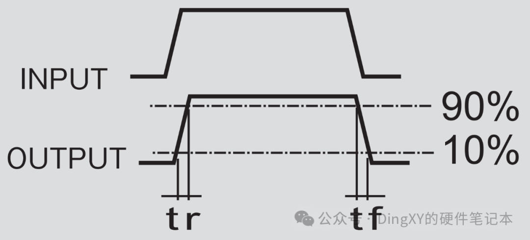
(1) The response time of the photointerrupter is illustrated in the diagram below.
① Rise Time (tr)
② Fall Time (tf)
(2) The signal transition of the photointerrupter is a slow analog signal change process, requiring several microseconds to reach a stable triggered or untriggered state.
(3) When the control chip reads the Vout analog signal from the photointerrupter, it determines whether the read data is 0 or 1 based on the corresponding level standard. When the control chip detects a transition from 0 to 1 or vice versa, it does not indicate that the photointerrupter state has stabilized.
(4) Therefore, when the control chip reads the photointerrupter state, the duration of the photointerrupter state must meet the rise time or fall time requirements specified in the manual before it can be considered that the state change of the photointerrupter has been completed.
2. Verilog Code (Send a private message with “photointerrupter_read” to obtain)
2.1 Function Description
Reads the photointerrupter signal, outputs the photointerrupter state, and outputs the flag signal for approaching and leaving the photointerrupter.
2.2 Source Code
Code details can be found on CSDN account https://blog.csdn.net/sinat_36503471?type=blog2.3 TestBench Simulation Code
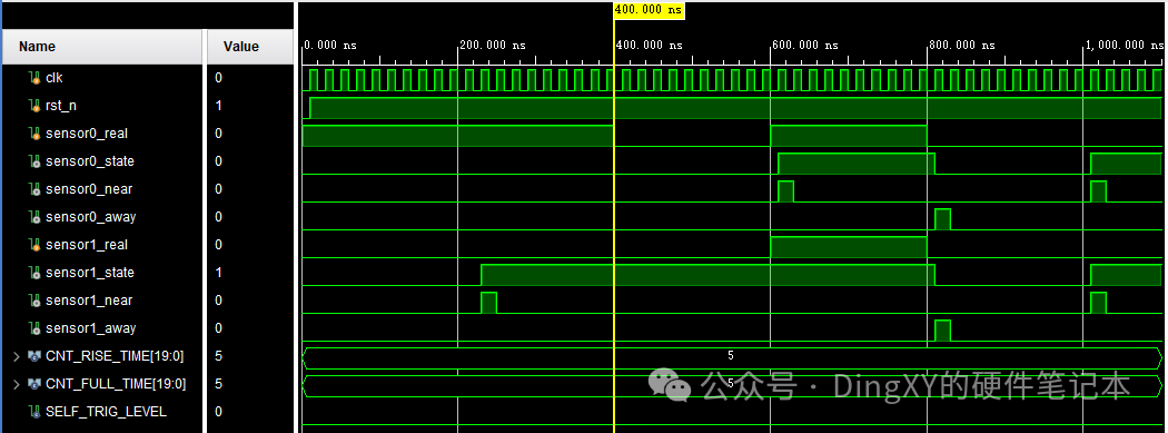
Code details can be found on CSDN account https://blog.csdn.net/sinat_36503471?type=blog2.4 Simulation Results
Note: The change in the photointerrupter state begins after 400ns. Before this, the sensor1_near flag signal is valid because the initial state of Sensor1 is triggered, and it is low-level triggered, which occurs during the process of confirming the initial state of the photointerrupter.