1 Overview
GigE Vision is a relatively complex protocol, and fully implementing it in an FPGA is quite challenging. If the FPGA is used as a receiver, only a small portion of the functionality needs to be implemented to configure the GigE Vision camera and perform image acquisition. This article trims the original structure of the GigE Vision protocol, retaining only the three main functions: device discovery, register configuration, and image acquisition. It successfully implements the configuration and real-time image acquisition of the Basler GIGE camera in the FPGA.
2 GigE Vision Protocol
The GigE Vision protocol consists of two parts: GVCP (GigE Vision Control Protocol) and GVSP (GigE Vision Streaming Protocol). GVCP is responsible for configuring the camera, while GVSP controls the transmission of image data.
2.1 GVCP Protocol
The GVCP protocol specifies the criteria for applications to configure and control external devices via Ethernet. The device configuration process uses commands (CMD) and acknowledgments (ACK). For example, in the case of an external host and a camera, the host first sends a command packet to the camera via Ethernet and then waits for the camera to return the acknowledgment packet for the current command; upon receiving the command packet, the camera executes the corresponding operation and then returns the acknowledgment packet to the host. The host, upon receiving the acknowledgment packet, determines whether the command was executed successfully based on the status information in the acknowledgment packet. If successful, it continues to send the next command packet; otherwise, it resends the current command packet. This method compensates for the connectionless nature of the UDP protocol, ensuring the integrity and reliability of data transmission.
GVCP includes two types of packets: command packets and acknowledgment packets. The header of the command packet is as follows:

In the command packet header, 0x42 is a fixed field for the GVCP command packet, the flag field contains specific information for different commands, the command field represents the type of command, the length field represents the length of the payload data in the command packet excluding the header (in bytes), and req_id represents the sequence number of the command packet.
The header of the acknowledgment packet is as follows:

In the acknowledgment packet header, the status field represents the execution status of the command packet, the acknowledge field represents the type of acknowledgment packet, the length field represents the length of the payload data in the acknowledgment packet excluding the header (in bytes), and ack_id represents the sequence number of the acknowledgment packet.
The design uses two types of command packets: device discovery (DISCOVERY) and write register (WRITEREG).
2.1.1 Device Discovery (DISCOVERY)
The device discovery command is used by the receiver (FPGA) to find GigE sending devices (cameras) in its subnet. This is achieved through the discovery command DISCOVERY_CMD.
Format of the discovery command packet:

The format of the discovery command packet in the design is:

The corresponding discovery acknowledgment packet DISCOVERY_ACK format is:
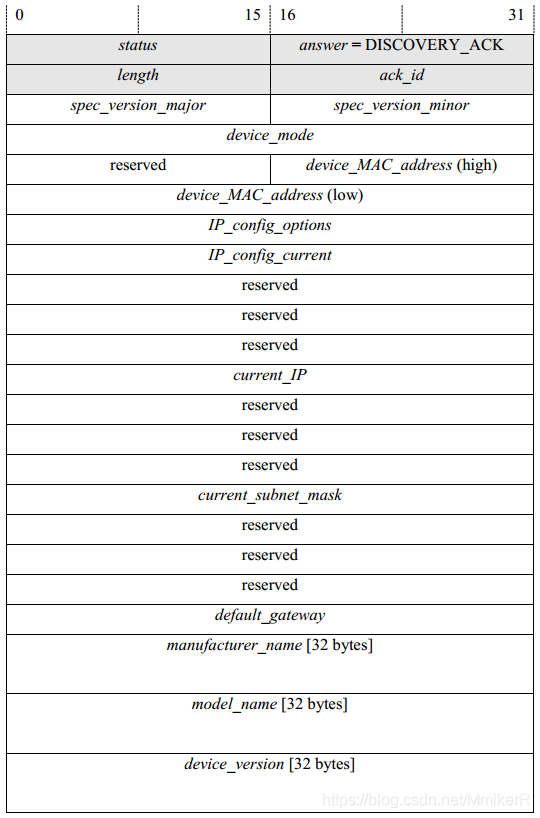
The discovery acknowledgment packet contains various key parameters of the camera, including the manufacturer, version, name, serial number, IP address, MAC address, etc., with a payload data length of 248 bytes. The design focuses on the camera’s IP address and MAC address information, where the MAC address is located in bytes 11 to 16 of the payload data, and the IP address is located in bytes 37 to 40.
2.1.2 Write Register (WRITEREG)
The write register command is used to configure the camera’s parameters, implemented through the WRITEREG_CMD command.
Format of the write register command packet:
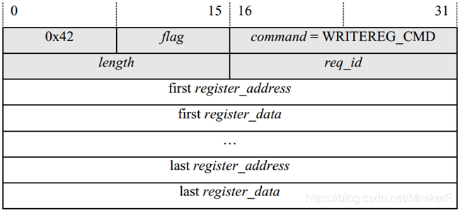
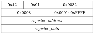
In the write register command packet, the register_address field represents the 32-bit register address, and the register_data field represents the 32-bit value to be written to the register. In the design, only one register is configured at a time, so it only contains one register_address and one register_data field.
Therefore, the format of the write register packet in the design is as follows:
The corresponding write register acknowledgment packet WRITEREG_ACK format is:
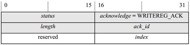
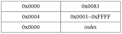
In the acknowledgment packet, the status field value is 0x0000, indicating that the write register command was executed successfully, and the index field represents the number of successfully configured registers. For configuring one register at a time, this field’s value is 0x0001.
Therefore, the format of the write register acknowledgment packet in the design is as follows:
2.2 GVSP Protocol
The GVSP protocol specifies a series of criteria for transmitting image data and image information from the GVSP sender to the GVSP receiver. The GVSP protocol transmits data in units of data blocks, typically using standard transmission mode. This mode includes three types of packets: header data packet (Data Leader Packet), payload data packet (Data Payload Packet), and trailer data packet (Data Trailer Packet). The header and trailer packets serve as the start and end delimiters for each data block and do not contain image data; the payload data packet serves as the carrier for the data in the data block and contains valid image data.
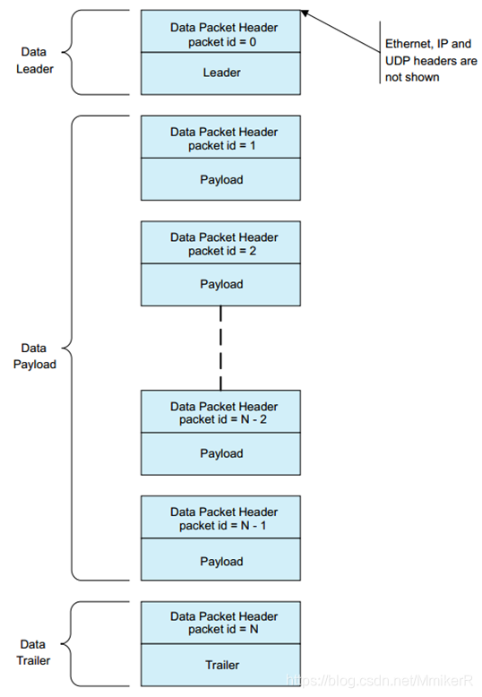
The three types of packets have the same GVSP header, formatted as follows:
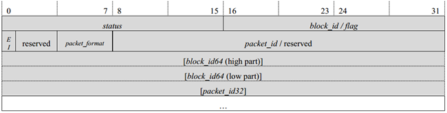
In the GVSP header, the status field represents the status of the packet, block_id represents the sequence number of the data block, packet_id represents the sequence number of the packet within the current data block (the packet_id of the header packet is always 0), and the packet_format field represents the type of packet (header packet, payload packet, trailer packet). The EI field indicates the flag for extending block_id and packet_id; when EI=0, block_id is 16 bits and packet_id is 24 bits, making the header length 8 bytes; when EI=1, block_id is 64 bits and packet_id is 32 bits, making the header length 20 bytes.
In the design, header and trailer packets are not processed; only payload data packets containing image data are extracted from the data stream based on the packet_format field. The length of the header is accurately determined by the EI bit, allowing for the effective image data to be obtained after stripping the header from the payload data packet. To ensure the real-time transmission of images, the status field is not checked, and erroneous image data is still output as valid data.
3 UDP IP Protocol
GigE Vision is based on the UDP protocol for data transmission. Therefore, to achieve GVCP and GVSP communication between the FPGA and the camera, a network communication protocol must also be designed. According to the requirements of the GigE Vision protocol, there are quite a few network protocols that need to be designed. From the perspective of achieving point-to-point data transmission between the FPGA and the camera, only the basic UDP, IP, and MAC protocols need to be implemented. Since the camera can be set to a fixed IP address, and both the camera’s IP address and MAC address can be obtained by sending the DISCOVERY command from the FPGA, the ARP protocol does not need to be implemented in the FPGA.
For the UDP and IP protocols, only the addition and removal of UDP and IP headers need to be implemented; other functionalities can be omitted. The MAC protocol is provided as an IP in the FPGA vendor’s development environment. Of course, one can also design a MAC, requiring only the basic functionalities of MAC header removal, addition, and CRC32 checksum.
4 FPGA Workflow
The entire process from camera configuration to image acquisition is as follows:
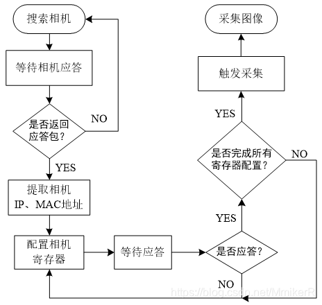
It can be divided into five steps, detailed as follows:
(1) The FPGA sends a UDP broadcast packet to search for the connected camera in its subnet. The UDP port number for GVCP is 3956; additionally, the IP addresses of the FPGA and the camera must belong to the same subnet; otherwise, the camera will not respond to the search packet.
(2) The FPGA waits for the camera to return the acknowledgment packet and extracts the camera’s IP address and MAC address from it, which will be used as the destination addresses in the IP and MAC headers of the data packets.
(3) The FPGA sends the write register command packet to configure the various functional registers of the camera and set its operational parameters.
(4) The FPGA sends the write acquisition enable register command packet to trigger the camera to perform image acquisition and transmission.
(5) The FPGA receives GVSP packets from the camera and extracts the valid image data from them.
Original link:
https://gitcode.csdn.net/66c6dc510bfad230b8ae756b.html
This article is for academic sharing only. If there is any infringement, please contact the backend for deletion processing.