


Introduction
This document mainly introduces the configuration and considerations of the GRMII, RGMII, and SGMII interfaces for the Quartus platform Triple-Speed Ethernet Intel FPGA IP. The version of the Quartus platform is Quartus Prime Pro 22.3. The FPGA device is Arria 10. The hardware mode is 1000BASE-T.
GMII
Core Configurations Configuration Interface
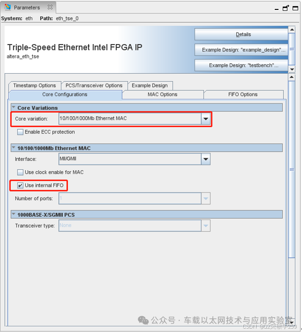
Select MAC type as 10/100/1000Mb Ethernet MAC.
Check to use internal FIFO cache.
MAC Options Configuration Interface
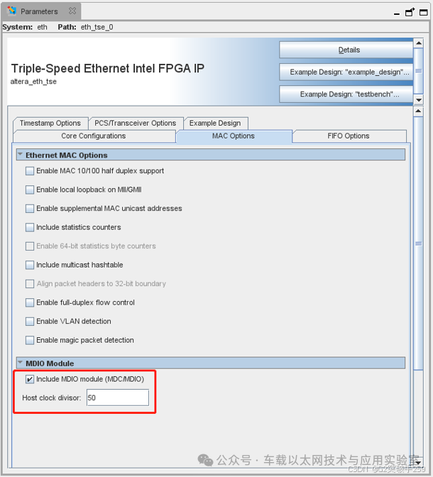
Depending on specific needs, different MAC function options can be checked:
Enable MAC 10/100 half duplex support
Enable this option to support half-duplex operation on 10/100 Mbps connections.
Enable local loopback on MII/GMII/RGMII
Enable this option to activate local loopback on the MAC’s MII, GMII, or RGMII interfaces. If this option is enabled, the loopback function can be dynamically enabled or disabled during system operation via the MAC configuration register.
Enable supplemental MAC unicast addresses
Enable this option to support MAC unicast addresses for hardware-based fast frame filtering.
Note:
The MAC address is a 48-bit (6-byte hexadecimal number) address used in Ethernet Layer 2 to identify device locations. The MAC address is divided into two parts: the first 24 bits are the Organizationally Unique Identifier (OUI), and the last 24 bits are assigned by the manufacturer.
MAC addresses can be classified as unicast, multicast, or broadcast. A unicast address identifies a single device or node, while a multicast address or group address represents a group of devices or nodes. The broadcast address is a special case of multicast, representing all addresses, denoted by all Fs: FF-FF-FF-FF-FF-FF. Of course, Layer 3 IP addresses also have unicast, multicast, and broadcast classifications.
A 48-bit MAC address is typically represented in 6 bytes of hexadecimal, such as XX-XX-XX-XX-XX. IEEE 802.3 specifies that the 48th bit of the Ethernet address indicates whether this address is a multicast or unicast address. If this bit is 0, it indicates that this MAC address is a unicast address; if this bit is 1, it indicates that this MAC address is a multicast address.
Include statistics counters
Enable this option to include support for Simple Network Management Protocol (SNMP) Management Information Base (MIB) and Remote Monitoring (RMON) statistics counter registers for incoming and outgoing Ethernet packets. By default, the width of all statistics counters is 32 bits.
Enable 64-bit statistics byte counters
Enable this option to extend the width of the selected statistics counters to 64 bits.
Include multicast hashtable
Enable this option to implement a hash table, which is a fast hardware-based mechanism for detecting and filtering multicast target MAC addresses in received Ethernet packets.
Align packet headers to 32-bit boundary
Enable this option to include logic that aligns all packet headers to a 32-bit boundary. This helps reduce software overhead when re-adjusting data buffers. This option can be used for MAC variants with a 32-bit wide internal FIFO buffer and those without an internal FIFO buffer. If you intend to use the Interniche TCP/IP protocol stack, this option must be enabled.
Enable full-duplex flow control
Enable this option to include logic for full-duplex flow control, which includes PAUSE frame generation and termination.
Enable VLAN detection
Enable this option to include logic for VLAN and stacked VLAN frame detection. When disabled, the MAC does not detect VLAN frames and bound VLAN frames. The MAC forwards these frames to the user application without processing.
Enable magic packet detection
Enable this option to include logic for magic packet detection (for Wake-on-LAN).
Include MDIO module (MDC/MDIO)
If you want to access external PHY devices connected to the MAC function, enable this option. When disabled, the core does not include logic or signals related to the MDIO interface.
Host clock divisor
Clock frequency settings for the MAC control interface, generating the MDC clock output on the MDIO interface. The default value is 40. For example, if the MAC control interface clock frequency is 100MHz, the MDC clock frequency is 100Mhz/40 = 2.5 MHz, so the divisor is set to 40. Intel recommends that the MDC frequency does not exceed 2.5 MHz.
For building a minimal system, the above options can be unchecked, but check the Include MDIO module (MDC/MDIO) option, as the external MAC control interface clock frequency is 125MHz, so the divisor is set to 50, and the MDC clock frequency is 125Mhz/50 = 2.5 MHz.
FIFO Options Configuration Interface
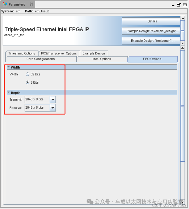
Set FIFO cache width and depth according to actual usage needs.
Other IP interfaces remain at default settings.
Instantiation Template
-
eth u0 (
-
.clk (_connected_to_clk_), // input, width = 1, control_port_clock_connection.clk
-
.reset (_connected_to_reset_), // input, width = 1, reset_connection.reset
-
.reg_addr (_connected_to_reg_addr_), // input, width = 8, control_port.address
-
.reg_data_out (_connected_to_reg_data_out_), // output, width = 32, .readdata
-
.reg_rd (_connected_to_reg_rd_), // input, width = 1, .read
-
.reg_data_in (_connected_to_reg_data_in_), // input, width = 32, .writedata
-
.reg_wr (_connected_to_reg_wr_), // input, width = 1, .write
-
.reg_busy (_connected_to_reg_busy_), // output, width = 1, .waitrequest
-
.ff_tx_clk (_connected_to_ff_tx_clk_), // input, width = 1, transmit_clock_connection.clk
-
.ff_rx_clk (_connected_to_ff_rx_clk_), // input, width = 1, receive_clock_connection.clk
-
.ff_rx_data (_connected_to_ff_rx_data_), // output, width = 8, receive.data
-
.ff_rx_eop (_connected_to_ff_rx_eop_), // output, width = 1, .endofpacket
-
.rx_err (_connected_to_rx_err_), // output, width = 6, .error
-
.ff_rx_rdy (_connected_to_ff_rx_rdy_), // input, width = 1, .ready
-
.ff_rx_sop (_connected_to_ff_rx_sop_), // output, width = 1, .startofpacket
-
.ff_rx_dval (_connected_to_ff_rx_dval_), // output, width = 1, .valid
-
.ff_tx_data (_connected_to_ff_tx_data_), // input, width = 8, transmit.data
-
.ff_tx_eop (_connected_to_ff_tx_eop_), // input, width = 1, .endofpacket
-
.ff_tx_err (_connected_to_ff_tx_err_), // input, width = 1, .error
-
.ff_tx_rdy (_connected_to_ff_tx_rdy_), // output, width = 1, .ready
-
.ff_tx_sop (_connected_to_ff_tx_sop_), // input, width = 1, .startofpacket
-
.ff_tx_wren (_connected_to_ff_tx_wren_), // input, width = 1, .valid
-
.ff_tx_crc_fwd (_connected_to_ff_tx_crc_fwd_), // input, width = 1, mac_misc_connection.ff_tx_crc_fwd
-
.ff_tx_septy (_connected_to_ff_tx_septy_), // output, width = 1, .ff_tx_septy
-
.tx_ff_uflow (_connected_to_tx_ff_uflow_), // output, width = 1, .tx_ff_uflow
-
.ff_tx_a_full (_connected_to_ff_tx_a_full_), // output, width = 1, .ff_tx_a_full
-
.ff_tx_a_empty (_connected_to_ff_tx_a_empty_), // output, width = 1, .ff_tx_a_empty
-
.rx_err_stat (_connected_to_rx_err_stat_), // output, width = 18, .rx_err_stat
-
.rx_frm_type (_connected_to_rx_frm_type_), // output, width = 4, .rx_frm_type
-
.ff_rx_dsav (_connected_to_ff_rx_dsav_), // output, width = 1, .ff_rx_dsav
-
.ff_rx_a_full (_connected_to_ff_rx_a_full_), // output, width = 1, .ff_rx_a_full
-
.ff_rx_a_empty (_connected_to_ff_rx_a_empty_), // output, width = 1, .ff_rx_a_empty
-
.mdc (_connected_to_mdc_), // output, width = 1, mac_mdio_connection.mdc
-
.mdio_in (_connected_to_mdio_in_), // input, width = 1, .mdio_in
-
.mdio_out (_connected_to_mdio_out_), // output, width = 1, .mdio_out
-
.mdio_oen (_connected_to_mdio_oen_), // output, width = 1, .mdio_oen
-
.gm_rx_d (_connected_to_gm_rx_d_), // input, width = 8, mac_gmii_connection.gmii_rx_d
-
.gm_rx_dv (_connected_to_gm_rx_dv_), // input, width = 1, .gmii_rx_dv
-
.gm_rx_err (_connected_to_gm_rx_err_), // input, width = 1, .gmii_rx_err
-
.gm_tx_d (_connected_to_gm_tx_d_), // output, width = 8, .gmii_tx_d
-
.gm_tx_en (_connected_to_gm_tx_en_), // output, width = 1, .gmii_tx_en
-
.gm_tx_err (_connected_to_gm_tx_err_), // output, width = 1, .gmii_tx_err
-
.m_rx_d (_connected_to_m_rx_d_), // input, width = 4, mac_mii_connection.mii_rx_d
-
.m_rx_en (_connected_to_m_rx_en_), // input, width = 1, .mii_rx_dv
-
.m_rx_err (_connected_to_m_rx_err_), // input, width = 1, .mii_rx_err
-
.m_tx_d (_connected_to_m_tx_d_), // output, width = 4, .mii_tx_d
-
.m_tx_en (_connected_to_m_tx_en_), // output, width = 1, .mii_tx_en
-
.m_tx_err (_connected_to_m_tx_err_), // output, width = 1, .mii_tx_err
-
.set_10 (_connected_to_set_10_), // input, width = 1, mac_status_connection.set_10
-
.set_1000 (_connected_to_set_1000_), // input, width = 1, .set_1000
-
.eth_mode (_connected_to_eth_mode_), // output, width = 1, .eth_mode
-
.ena_10 (_connected_to_ena_10_), // output, width = 1, .ena_10
-
.tx_clk (_connected_to_tx_clk_), // input, width = 1, pcs_mac_tx_clock_connection.clk
-
.rx_clk (_connected_to_rx_clk_) // input, width = 1, pcs_mac_rx_clock_connection.clk
-
);
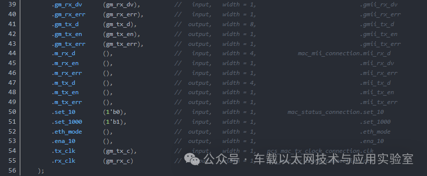
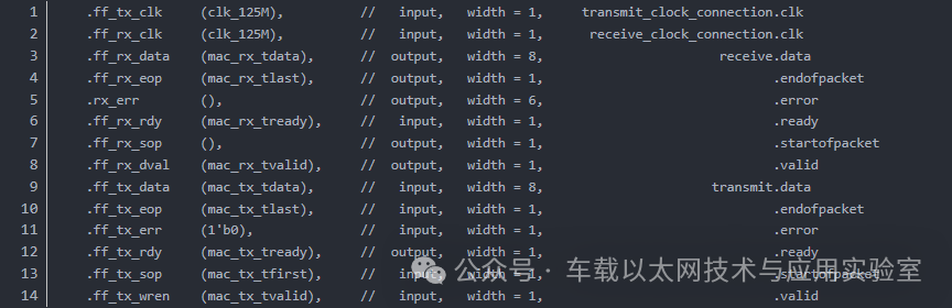
Among them, the interfaces that must be connected are as follows
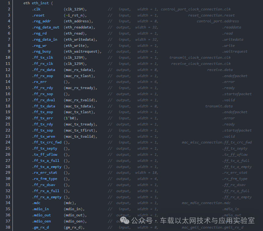
Interface Explanation
The following interfaces are the MAC configuration interfaces, connecting to the MAC configuration module.

The following interfaces are the MAC transmission interfaces, connecting to the UDP module.
The transport layer uses the UDP protocol, and the UDP module is an OpenCores open-source module.
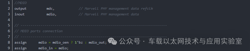
The following interfaces are the PHY management interfaces.

The following interfaces are the MAC status interfaces.
Configured for gigabit mode.

The following interfaces are GMII interfaces.

RGMII
Starting from Intel Quartus Prime software version 17.1, the RGMII interface is not supported in Intel Stratix 10, Intel Arria 10, and Intel Cyclone 10 GX devices.
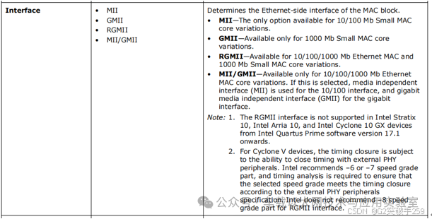
Therefore, the IP configuration for RGMII is the same as for GMII, and the gmii_rgmii_bridge module is used externally to implement the conversion between the RGMII interface and the GMII interface.
Instantiation Template
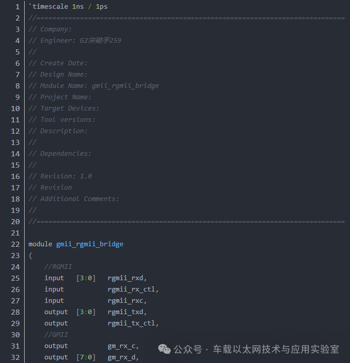
gmii_rgmii_bridge
The source code for the gmii_rgmii_bridge module is as follows:
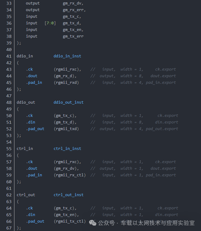

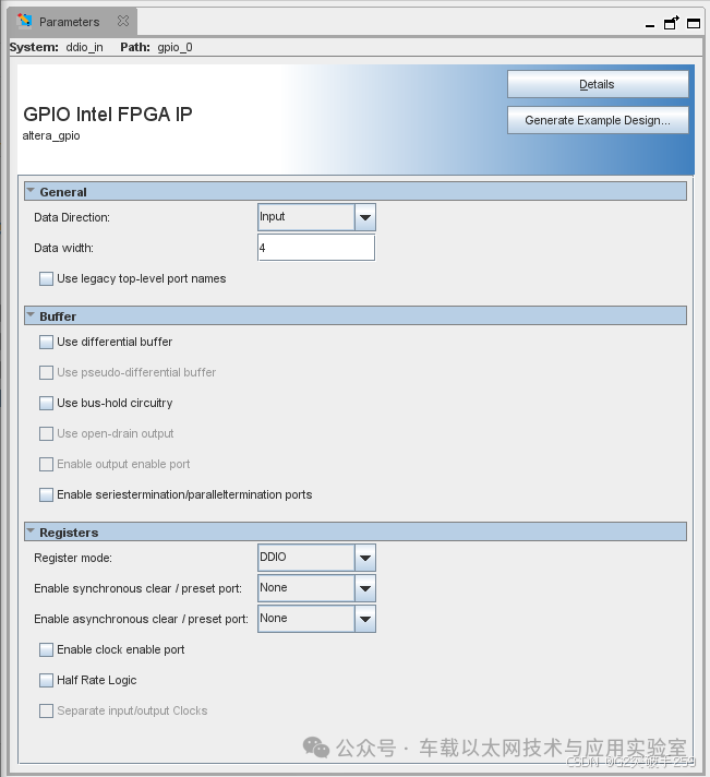
The ddio_in configuration interface is shown below:
The ddio_out configuration interface is shown below:
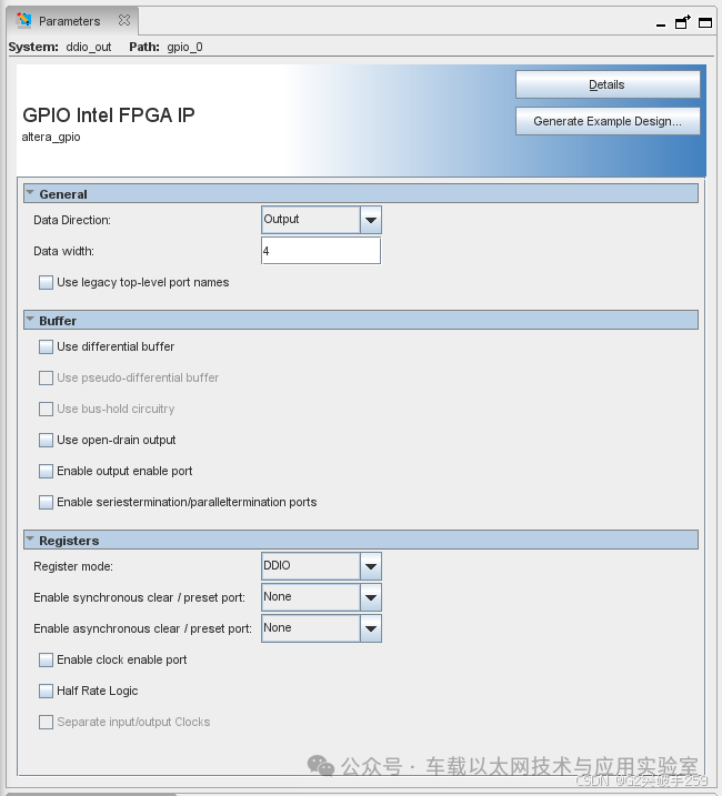
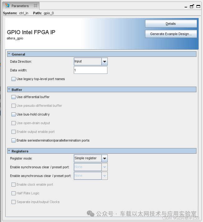
The ctrl_in configuration interface is shown below:
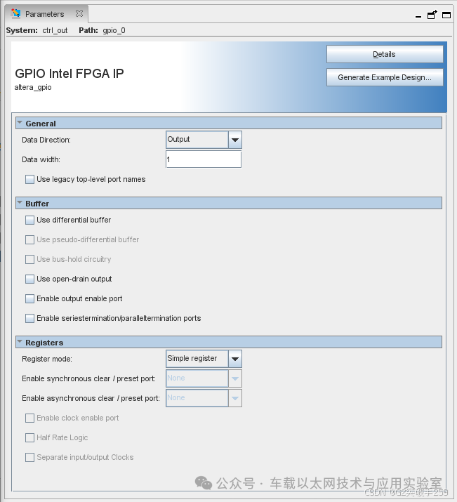
The ctrl_out configuration interface is shown below:
SGMII
Core Configurations Configuration Interface
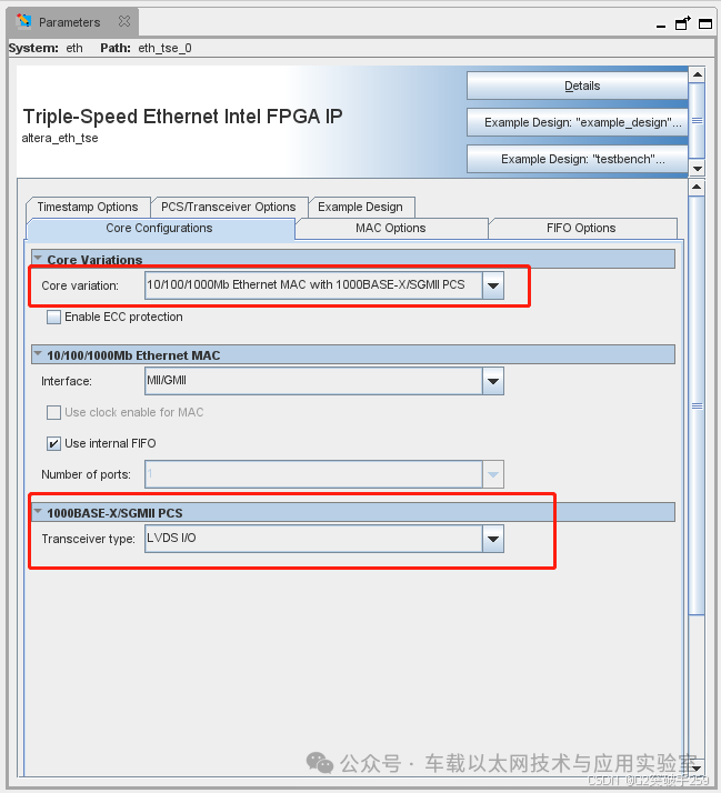
Select MAC type as 10/100/1000Mb Ethernet MAC with 1000BASE-X/SGMII PCS. Choosing this type, the IP user interface is the same as GMII and RGMII MAC transmission interfaces, making it more convenient to connect to the UDP module. If you select 1000BASE-X/SGMII PCS only, the IP user interface is a GMII interface, implementing the conversion function between GMII and SGMII interfaces.
For the PCS Transceiver type, select LVDS I/O, or GXB can be selected based on hardware design. Here, LVDS I/O is chosen due to limited GXB resources. When allocating FPGA IO, the following points need to be noted:
1. SGMII’s TX and RX, the LVDS reference clock needs to be placed in the same bank.
2. To prevent potential performance issues, ensure that the LVDS reference clock directly uses a dedicated reference clock input within the same I/O bank. It is not recommended to manually boost the reference clock.
3. RX should be placed on differential pins that support Soft-CDR functionality. The RX interface must be placed in the same I/O bank, and each bank has only 12 PCLK resources, so only 12 Soft-CDR channels are available. To understand which pin pairs in each bank can support Soft-CDR channels, refer to the device pin output file. In the device pin output file, “Dedicated Tx/Rx Channel” lists the available LVDS pins.

If the pin pair is even, it indicates that the pin pair supports Soft-CDR mode. This is necessary; otherwise, the following error will occur.

Other IP interface configurations are consistent with GMII.
Instantiation Template
-
eth u0 (
-
.ff_tx_clk (_connected_to_ff_tx_clk_), // input, width = 1, transmit_clock_connection.clk
-
.ff_rx_clk (_connected_to_ff_rx_clk_), // input, width = 1, receive_clock_connection.clk
-
.ff_rx_data (_connected_to_ff_rx_data_), // output, width = 8, receive.data
-
.ff_rx_eop (_connected_to_ff_rx_eop_), // output, width = 1, .endofpacket
-
.rx_err (_connected_to_rx_err_), // output, width = 6, .error
-
.ff_rx_rdy (_connected_to_ff_rx_rdy_), // input, width = 1, .ready
-
.ff_rx_sop (_connected_to_ff_rx_sop_), // output, width = 1, .startofpacket
-
.ff_rx_dval (_connected_to_ff_rx_dval_), // output, width = 1, .valid
-
.ff_tx_data (_connected_to_ff_tx_data_), // input, width = 8, transmit.data
-
.ff_tx_eop (_connected_to_ff_tx_eop_), // input, width = 1, .endofpacket
-
.ff_tx_err (_connected_to_ff_tx_err_), // input, width = 1, .error
-
.ff_tx_rdy (_connected_to_ff_tx_rdy_), // output, width = 1, .ready
-
.ff_tx_sop (_connected_to_ff_tx_sop_), // input, width = 1, .startofpacket
-
.ff_tx_wren (_connected_to_ff_tx_wren_), // input, width = 1, .valid
-
.ff_tx_crc_fwd (_connected_to_ff_tx_crc_fwd_), // input, width = 1, mac_misc_connection.ff_tx_crc_fwd
-
.ff_tx_septy (_connected_to_ff_tx_septy_), // output, width = 1, .ff_tx_septy
-
.tx_ff_uflow (_connected_to_tx_ff_uflow_), // output, width = 1, .tx_ff_uflow
-
.ff_tx_a_full (_connected_to_ff_tx_a_full_), // output, width = 1, .ff_tx_a_full
-
.ff_tx_a_empty (_connected_to_ff_tx_a_empty_), // output, width = 1, .ff_tx_a_empty
-
.rx_err_stat (_connected_to_rx_err_stat_), // output, width = 18, .rx_err_stat
-
.rx_frm_type (_connected_to_rx_frm_type_), // output, width = 4, .rx_frm_type
-
.ff_rx_dsav (_connected_to_ff_rx_dsav_), // output, width = 1, .ff_rx_dsav
-
.ff_rx_a_full (_connected_to_ff_rx_a_full_), // output, width = 1, .ff_rx_a_full
-
.ff_rx_a_empty (_connected_to_ff_rx_a_empty_), // output, width = 1, .ff_rx_a_empty
-
.mdc (_connected_to_mdc_), // output, width = 1, mac_mdio_connection.mdc
-
.mdio_in (_connected_to_mdio_in_), // input, width = 1, .mdio_in
-
.mdio_out (_connected_to_mdio_out_), // output, width = 1, .mdio.out
-
.mdio_oen (_connected_to_mdio_oen_), // output, width = 1, .mdio_oen
-
.clk (_connected_to_clk_), // input, width = 1, control_port_clock_connection.clk
-
.reset (_connected_to_reset_), // input, width = 1, reset_connection.reset
-
.reg_data_out (_connected_to_reg_data_out_), // output, width = 32, control_port.readdata
-
.reg_rd (_connected_to_reg_rd_), // input, width = 1, .read
-
.reg_data_in (_connected_to_reg_data_in_), // input, width = 32, .writedata
-
.reg_wr (_connected_to_reg_wr_), // input, width = 1, .write
-
.reg_busy (_connected_to_reg_busy_), // output, width = 1, .waitrequest
-
.reg_addr (_connected_to_reg_addr_), // input, width = 8, .address
-
.ref_clk (_connected_to_ref_clk_), // input, width = 1, pcs_ref_clk_clock_connection.clk
-
.led_crs (_connected_to_led_crs_), // output, width = 1, status_led_connection.crs
-
.led_link (_connected_to_led_link_), // output, width = 1, .link
-
.led_panel_link (_connected_to_led_panel_link_), // output, width = 1, .panel_link
-
.led_col (_connected_to_led_col_), // output, width = 1, .col
-
.led_an (_connected_to_led_an_), // output, width = 1, .an
-
.led_char_err (_connected_to_led_char_err_), // output, width = 1, .char_err
-
.led_disp_err (_connected_to_led_disp_err_), // output, width = 1, .disp_err
-
.rx_recovclkout (_connected_to_rx_recovclkout_), // output, width = 1, serdes_control_connection.export
-
.rxp (_connected_to_rxp_), // input, width = 1, serial_connection.rxp_0
-
.txp (_connected_to_txp_) // output, width = 1, .txp_0
-
);
Among them, the interfaces that must be connected are as follows
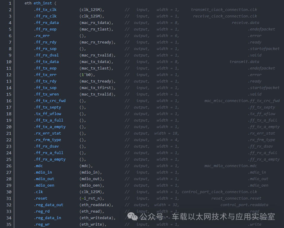
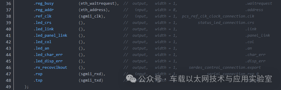
Interface Explanation
The following interfaces are SGMII interfaces.

It should be noted that SGMII uses the without CLK mode, where the sgmii_clk is the reference clock of the PCS, connected to a 125MHz crystal oscillator.

Disclaimer: We respect originality and emphasize sharing; the text and images are copyrighted by the original authors. The purpose of reprinting is to share more information and does not represent the position of this account. If your rights are infringed, please contact us in a timely manner, and we will delete it as soon as possible. Thank you!
Original link:
https://blog.csdn.net/s1_mple/article/details/144603047