
In real life, we always need to interact with others and share information. Microcontrollers also need to communicate with various devices. For example, the display instrument in a car needs to know the engine speed and the operating parameters of the motor, so the display instrument must obtain data from the car’s underlying controller. This data acquisition process is a communication process. Similar examples include communication between controllers, which are usually microcontrollers or PLCs, and frequency converters. Both parties in the communication must adhere to a set of established rules, also known as protocols, just like our conversations, which require both parties to follow a set of grammatical rules to achieve dialogue.
Communication protocols are divided into hardware layer protocols and software layer protocols. Hardware layer protocols mainly specify the physical wiring, transmission level signals, and the order of transmission, among other hardware characteristics. Common hardware protocols include serial ports, IIC, SPI, RS485, CAN, and USB. Software layer protocols focus more on the specifications of upper-layer applications, such as the Modbus protocol. Here, we will focus on the serial communication protocol of the 51 microcontroller, hereinafter referred to as the serial port. The six characteristics of the serial port are as follows. (1) At least three physical connections: Tx data transmission line, Rx data reception line, and GND common ground line.
(2) The agreement of 0 and 1. For RS232 levels, a voltage signal between -5V and -25V is defined as 1, while a voltage signal between +5V and +25V is defined as 0. For TTL levels, a voltage signal of 5V is defined as 1, and a voltage signal of 0V is defined as 0. For CMOS levels, a voltage signal of 3.3V is defined as 1, and a voltage signal of 0V is defined as 0. CMOS levels are generally used in ARM chips.
(3) Transmission order. The low bit is sent first.
(4) Baud rate. A data bit (0 or 1) is maintained on the data transmission line for a time agreed upon by both parties. It can also be understood as the number of bits that can be transmitted per second. Common baud rates include 300 bit/s, 600 bit/s, 2400 bit/s, 4800 bit/s, and 9600 bit/s.
(5) The start signal for communication. When the sender is not sending data, it should set Tx to 1. When it needs to send, it first sets Tx to 0 and maintains it for one bit time. The receiver continuously monitors Rx, and if it detects that Rx has been high for a long time and then suddenly goes low (set to 0), it is considered that the sender is about to send data, quickly starting its own timer to ensure that the timers of both sender and receiver are synchronized.
(6) Stop signal. After the sender sends the last valid bit, it must keep Tx high for one bit time, which is the stop bit.
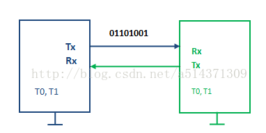
Now, let’s move on to an experiment where we will send a byte from the 51 microcontroller to the computer’s serial port debugging assistant. The purpose of this experiment is to master the sending and receiving process of the serial communication protocol.
Virtual Serial Port
Experiment 1: Virtual Serial Port Experiment
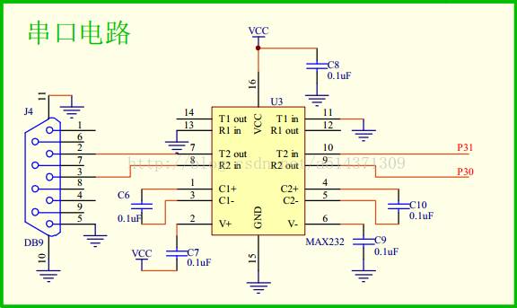
Generally, microcontrollers have dedicated serial port pins, and in the 51 microcontroller, they are P3.0 and P3.1. These pins have the hardware circuit for the serial port, so using them does not require setting the signal sending stop. To master the protocol, we will use other pins to simulate the serial port, hence the name virtual serial port. Here we choose P1.0, but note that our 51 microcontroller must send data to the computer through a serial-to-USB device (i.e., converting TTL level to RS232 level), and since our development board only connects P3.0 and P3.1 to the serial-to-USB device, we can short P1.0 to P3.1. The following diagram shows the principle of this serial-to-USB connection.
Now, let’s get straight to the code.
#include "reg51.h"/* Make P1.0 act as the serial transmission pin TX Send data at a baud rate of 9600bit/s Since the baud rate is 9600bit/s, the time to send one bit is t=1000000us/9600=104us */sbit TX=P3^1; //P1^0 output TTL signal, need to transferred to rs232 signal, can be connected to P3^1 #define u16 unsigned int //Macro definition #define u8 unsigned char u8 sbuf; bit ti=0; void delay(u16 x){ while(x--); } void Timer0_Init(){ TMOD |= 0x01; TH0=65440/256; TH0=65440%256; TR0=0; } void Isr_Init(){ EA=1; ET0=1; } void Send_Byte(u8 dat){ sbuf=dat;//By introducing the global variable sbuf, we can save the parameter dat TX=0; //A start bit TR0=1; while(ti==0); //Wait for sending to complete ti=0; //Clear the sending completion flag } void TF0_isr() interrupt 1 //Enter the interrupt every 104us { static u8 i; //Record the number of times the interrupt is entered TH0=65440/256; TL0=65440%256; i++; if(i>=1 &&& i<=8) { if((sbuf&(1<<(i-1)))==0) // (sbuf&(1<<(i-1))) indicates to extract the i-1 bit { TX=0; } else { TX=1; } } if(i==9) //Stop bit { TX=1; } if(i==10) { TR0=0; i=0; ti=1; //Sending completed } } void main(){ TX=1; //Set TX to idle state Timer0_Init(); Isr_Init(); while(1) { Send_Byte(65); //0x41 delay(60000); } }The experiment introduces Timer 0 to control the holding time of each bit on the transmission line. First, the main function is entered, and TX is set to 1 to keep the transmission line idle, at which point both the sender and receiver are idle. Next, Timer 0 is initialized, and TR0 is set to 0, indicating that Timer 0 should not be started yet. Then, the interrupt system is initialized, and at this point, the interrupt system is already enabled. Entering the while loop, the Send_Byte() function is called first, passing 65 to the parameter dat, which then assigns 65 to sbuf, completing the preparation work. Next, TX is set to 0, which is the start bit, and this start bit must be maintained for 104us. Then, Timer TR0 is started by setting it to 1, and the timer begins counting. When the first overflow occurs, which is after 104us, the interrupt is entered, and the receiver also detects this sudden drop in signal, quickly starting its own timer. After entering the interrupt subroutine, the timer initial value is reloaded, and i is incremented. When i=1, the lowest bit of the data should be sent, with a total of 8 bits of data, so a conditional statement if(i>=1 && i<=8) is used to determine whether the data bits have been sent. Then, by using if(i==9), the stop bit is sent, and finally, when i=10, which means the sending is complete, the timer must be turned off (thus the program also ends), and i is set to 0, and ti is set to 1 (to exit the while(ti==0) loop), and finally, ti is set to 0 to ensure that the program stays in while(ti==0) for the next byte to be sent.
On-Chip Serial Port
The above discussed the virtual serial port, and the pins related to the serial port mentioned earlier, P3.0 and P3.1, actually the 51 microcontroller has an on-chip serial port. So how should this serial port be used?
The on-chip serial port supports synchronous and asynchronous modes. In simple terms, synchronous mode means there is a clock line, while asynchronous mode does not have a clock line. The clock line refers to a dedicated line used to transmit clock signals during synchronous communication, which is used to synchronize with each bit to avoid timing errors introduced by using timers in asynchronous communication.
The on-chip serial port also supports 8-bit and 9-bit modes. As shown in the following diagram.
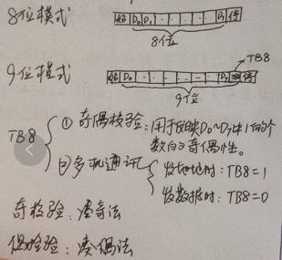
Where D0-D7 represents the 8 bits of a byte. The 9-bit mode simply adds an extra bit TB8, which is used for parity checking or multi-device communication. The principle of parity checking will not be analyzed here. In multi-device communication, for example, the host only sends data to a device with the address 0x02 in the network, TB8 is set to 1, and the preceding D0-D7 represents the address 0x02, then TB8 is set to 0, and the preceding D0-D7 represents the data.
After setting the mode of the on-chip serial port, the baud rate of the serial port must also be set.
The baud rate of the on-chip serial port is equal to the overflow rate of Timer 1 operating in mode 2 divided by 32. If Timer 1 is to operate in mode 2, then TMOD=0x20. Additionally, to ensure a division by 32, we must also set the initial value of the counter. Assuming the crystal oscillator is 11.0592MHz, the timer’s counting pulse is F=f/12, so the time for each pulse of the timer is T=12/f. Let the starting point of the counter be x, then the number of pulses to be counted for one overflow is (256-x). Therefore, when the counting starting point is x, the time for one overflow is t=12/f*(256-x). The corresponding overflow rate is 1/t=f/(12*(256-x)). The corresponding baud rate is b=f/(384*(256-x)).
x=256-f/(384*b)
Where f is the crystal frequency, b is the desired baud rate, and x is the initial value TH1 of the timer.
For example, when the crystal frequency is 11.0592M and the desired baud rate is 9600bit/s, then TH1=253. As a side note, we can also calculate that under other common baud rates, TH1 is always an integer. This explains why the 51 microcontroller uses an 11.0592M crystal instead of 12M, ensuring that the timing of the serial port is more accurate, although it sacrifices the accuracy of the timer.
Experiment 2: Sending a Byte via External Serial Port.
Now let’s start our experimental journey. Let’s look at the code directly.
#include "reg51.h"
#define u16 unsigned int
#define u8 unsigned char
void delay(u16 x){
while (x--);
}
void Uart_Init() //Serial port initialization {
    SCON = 0x50; //8-bit asynchronous mode
    TMOD |= 0x20; //Timer 1 working mode 2
    TH1 = 253; //9600bit/s
    TR1 = 1;
}
void Send_Byte(u8 dat){
    SBUF = dat; //Start sending, just need to give the content to be sent to the SBUF register
while (TI == 0); //Wait for sending to complete, because TI is 1 when the stop bit is being sent
    TI = 0;
}
void main(){
    Uart_Init();
while (1)
    {
        Send_Byte('m');
        delay(60000);
    }
}
Experiment 2 has significantly reduced the code compared to Experiment 1, and there is no need to consider the complicated bit sending timing. You just need to understand the usage of the registers SCON, TMOD, TCON, and SBUF. TI is the first bit in SCON, which is the send interrupt request flag. In this mode, when the stop bit starts sending, it is set by internal hardware, and after responding to the interrupt, TI must be cleared by software.
Experiment 3: Sending a String via On-Chip Serial Port
Having introduced how to send a byte, how do we send a string or even text? Here we first introduce the concept of a string.
A string is a sequence of ASCII codes for multiple characters stored consecutively starting from a certain address in memory, with a 0 stored after the last character, and this contiguous memory space is called a string, with the final 0 being the string terminator. Note that this 0 is not the same concept as the 0 in single quotes, which refers to the ASCII code of 0.
The relationship between arrays and strings: a string is a special case of an array, and an array can be treated as a string under certain conditions. In C language, a string is described using double quotes, such as “abcd”.
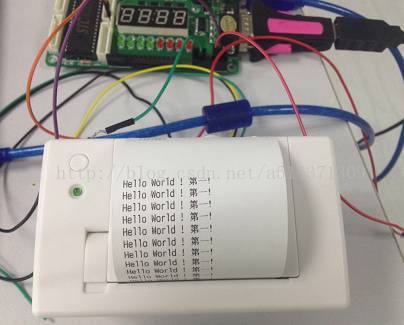
Next, we will demonstrate how to send a string through an experiment. The goal of our experiment is to print the string “Hello World! 第一!” to the printer. Let’s get straight to the code.
#include "reg51.h"
#define u16 unsigned int  #define u8 unsigned char  void delay(u16 x){  while(x--);  }  void Uart_Init() //Serial port initialization  {      SCON=0x50; //8-bit asynchronous mode      TMOD|=0x20; //Timer 1 working mode 2      TH1=253;//9600bit/s      TR1=1;  }  void Send_Byte(u8 dat)    //Send a byte via serial port  {      SBUF=dat; //Start sending, just need to give the content to be sent to the SBUF register  while(TI==0); //Wait for sending to complete, because TI is 1 when the stop bit is being sent      TI=0;  }void Send_String(u8 *str)   //Send a string  *str is the address of the first character of the string  {      abc:      //Label  if(*str != 0)      {  Send_Byte(*str);  str++;  goto abc;         }   }    void main(){      Uart_Init();  while(1)      {  Send_String("Hello World! 第一!");  Send_Byte(10);         delay(60000);         delay(60000);      }  }
Experiment Effect
‧‧‧‧‧‧‧‧‧‧‧‧‧‧‧ END ‧‧‧‧‧‧‧‧‧‧‧‧‧‧‧