Today, I will share why pull-up resistors are necessary on I2C signal lines.
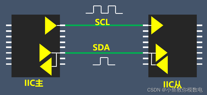
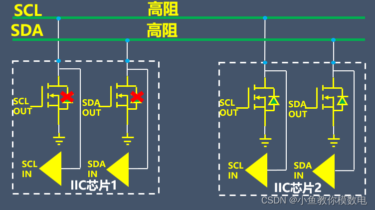
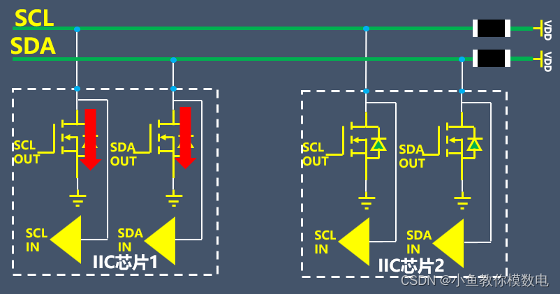
The main reason is that the SDA and SCL pins of I2C chips are open-drain outputs, meaning they only have one NMOS transistor, unlike push-pull outputs which have two MOS transistors.
When the MOS transistor connected to the SDA and SCL pins outputs, the I2C signal line level is low.
When the MOS transistor connected to the SDA and SCL pins is turned off, if there is no pull-up resistor, the I2C signal line is in a high-impedance state, and the level is unknown since open-drain outputs cannot provide a high signal.
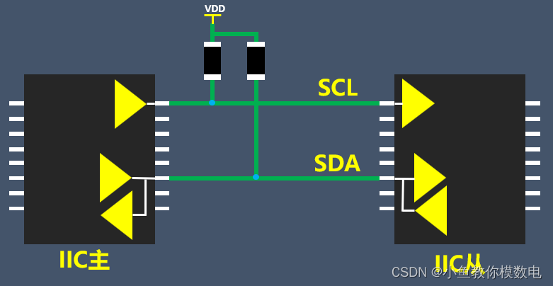
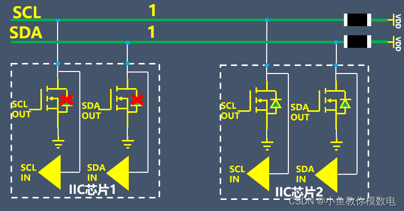
Therefore, after adding a pull-up resistor, when the MOS transistor connected to the SDA and SCL pins is turned off, the level on the I2C signal line is a definite high level.
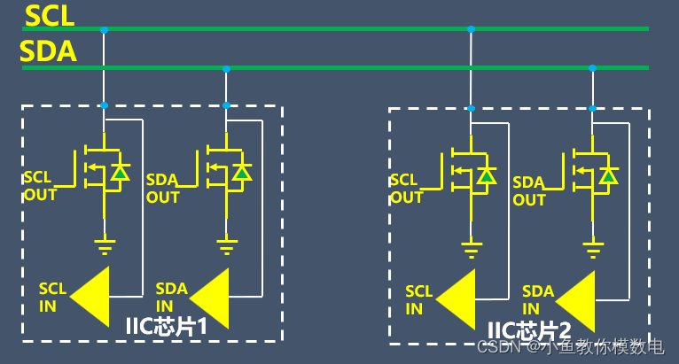
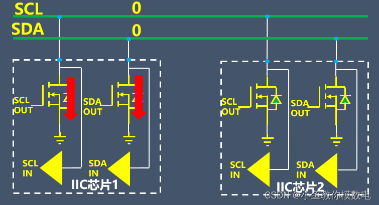
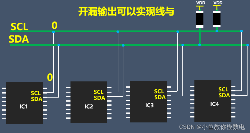
When multiple I2C devices are connected through the I2C bus, this requires that the I2C devices can implement a wired AND function, and since the I2C pins of the chip are open-drain outputs, this works well. As long as one I2C device’s pin level is low, the corresponding SCL or SDA bus will also become low. If the I2C device pins are push-pull outputs, connecting multiple I2C devices on the same bus can easily damage the chips.
Value of I2C Pull-Up Resistors
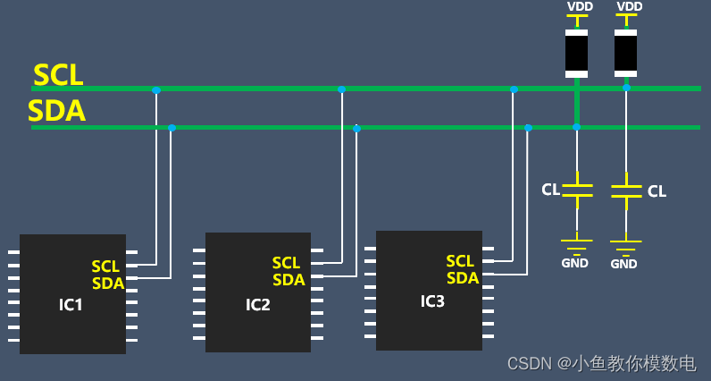
The value of the pull-up resistor for I2C signals cannot be too high because the SCL and SDA pins of I2C chips have parasitic capacitance, and the traces for SDA and SCL signals also have parasitic capacitance. The entire I2C bus effectively connects to a load capacitance Cl.
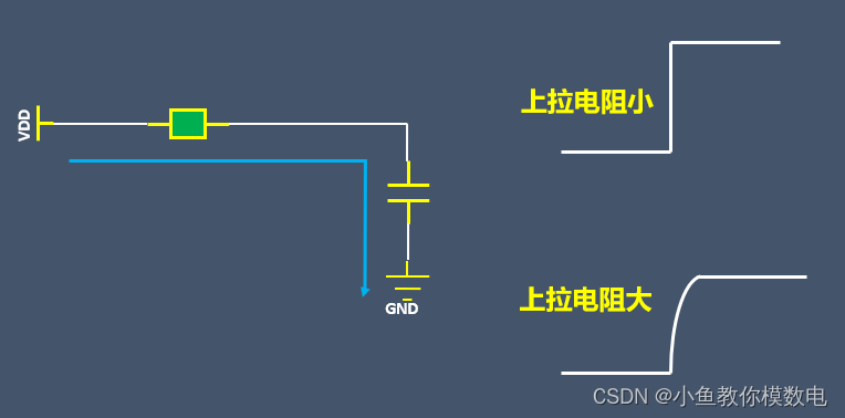
If the pull-up resistor is too large, the driving capability of the I2C bus for high levels is poor. When the bus level changes from 0 to 1, it effectively acts as an RC charging circuit; the larger the pull-up resistor, the slower the rising edge of the waveform, which can affect the timing of the I2C communication and may result in errors. Therefore, this pull-up resistor cannot be too large.
The rise time of I2C SDA and SCL signals and the bus capacitance have different requirements under different modes, as shown in the table below.
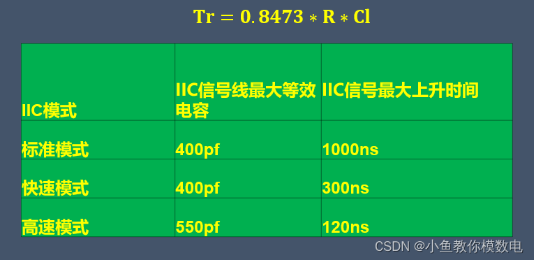
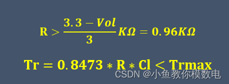
The rise time of the I2C bus signal can be calculated using the formula Tr=0.8473*R*Cl, where Cl is the equivalent load capacitance of the I2C bus.
The pull-up resistor for I2C signals also cannot be too small. If it is too small, when the I2C pin outputs a low level, the current flowing into the I2C pin of the chip will increase, which may cause the low level of the I2C signal line to rise, and excessive IO current could potentially damage the chip.
Generally, we require that when the I2C pin is at a low level, the current flowing through the I2C pin of the chip should be less than 3mA. So if we are pulling up to 3.3V, the resistor must satisfy R>(3.3-VoL)l3KΩ=0.96KΩ, where VoL is the maximum voltage when the I2C pin is low, generally about 0.4V. Combining this with the previous formula allows us to determine the range of values for the pull-up resistor.
The power supply voltage determines the minimum value of the pull-up resistor, while the bus load capacitance determines the maximum value of the pull-up resistor.
Commonly used values for I2C signal pull-up resistors are 4.7K, generally less than 10K and greater than 1K. If the I2C bus is relatively long and has many devices, the resistance can be lowered appropriately.
If many I2C devices are connected to the I2C bus, do we need to add a pull-up resistor for each I2C device?
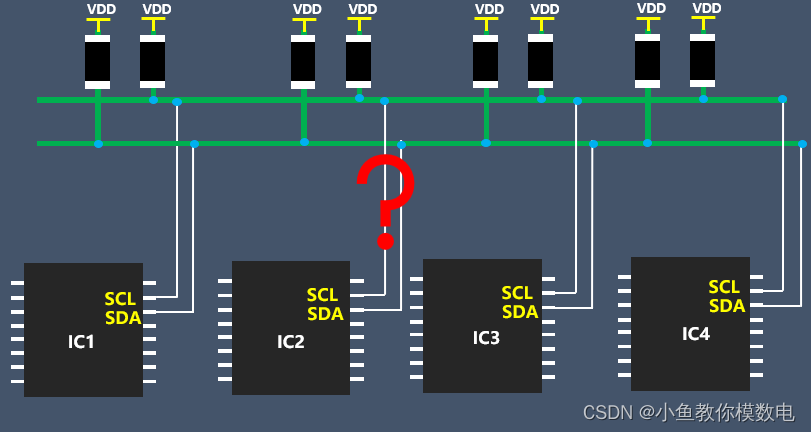
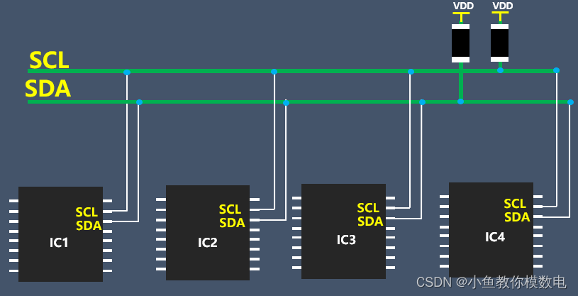
The answer is no. We only need to add a pull-up resistor at appropriate locations along the SDA and SCL lines. If each device has a pull-up, it will be like these resistors are in parallel, reducing the overall resistance value. There are generally no specific requirements for the locations of the pull-up resistors, but they are usually placed at the end of the I2C line.
Source: The internet, copyright belongs to the original author. If there is any infringement, please contact for deletion.
Click👇 to follow, set as a star in the right menu bar···

What’s the importance of an engineer’s surname? This surname is the most awkward! Please stop calling me “Mr. X”!
Animated graphics to quickly understand commonly used communication protocols, save!