To start, why do I write IIC instead of I2C in my article? Because they are the same thing, and it’s easier for me to write as IIC 
Today, we will look at how to use IIC in the STC library functions.
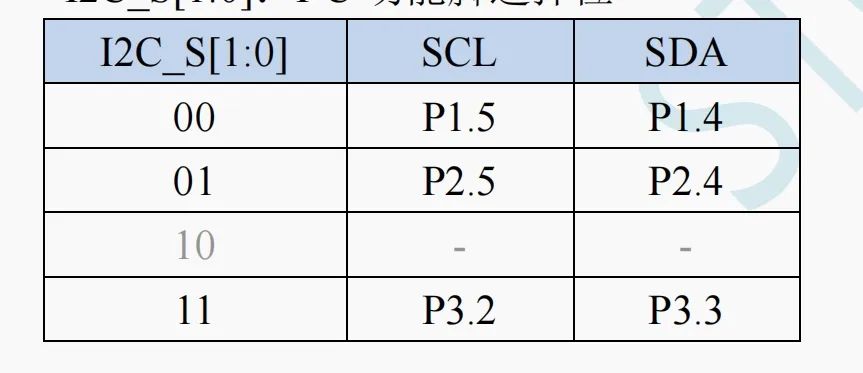
There are three sets of pins available for us to choose from, and as usual, we need to include the header file STC32G_Switch.h.
We can use the function below to select the pins. Just change the parameters inside to switch to other pins.
I2C_SW(I2C_P24_P25);The STC IIC does not have bus arbitration functionality, so if needed, we have to use software IIC and implement it ourselves.
There are master and slave modes, but generally, it is used as a master, so I will not discuss the slave aspect.
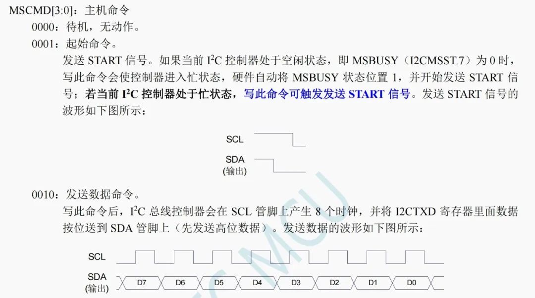
Once we configure IIC, we just need to rewrite the IIC master control register to generate the corresponding IIC timing.
Some of you might wonder, didn’t I say this series only uses library functions? Can’t we avoid discussing registers?
About this, I will reveal why shortly. Let’s look directly at the library functions.
We will include files STC32G_I2C.c and STC32G_I2C_Isr.c in the project.
Use the function below to configure IIC.
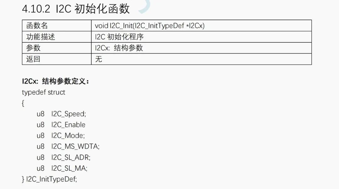
Use a pointer to a structure variable to configure IIC.
The structure members from top to bottom are:
IIC speed: though it’s called speed, we actually fill in a prescaler value.
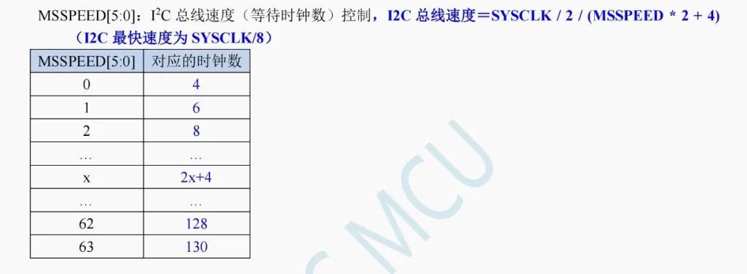
The IIC rate is the system clock/2 divided by this coefficient multiplied by two and plus 4. For example, if our system clock is 24MHz and I want to control the IIC rate to 100k, then I would fill in 58.
The next is the enable bit, set it to ENABLE.
Select the mode as master mode, I2C_Mode_Master.
Whether to automatically send data means that when we write the data to be sent into the corresponding register, it automatically sends and receives an ACK response. This depends on the situation; I set it to DISABLE.
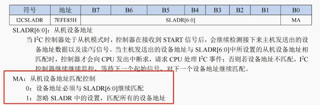
The slave address is filled in if we are acting as a slave, meaning we can fill in a seven-bit address. If we are in master mode, we can leave it blank.
For the slave address matching, I didn’t quite understand it. If I’m a slave, what address do I need to match? So I included the explanation from the official documentation below. Fortunately, generally in master mode, there is no need to configure slave-related settings.
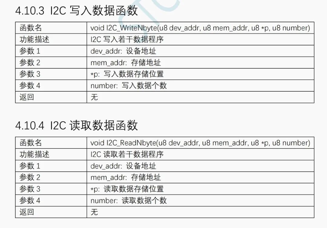
Next, there are two functions for sending and receiving data.
But I don’t plan to use them.
Because using those two, I cannot read data from SGP30 (I can, but it’s cumbersome).
You can review my previous article on SGP30 to see how to communicate with SGP30.
[Hardware Module] SGP30 Gas Sensor
In summary, we first send two bytes of commands, 0x20 and 0x03, to initialize the SGP30. Then, to get gas data, we send two bytes of commands, 0x20 and 0x08, to collect data, followed by receiving 6 bytes of data. The first two bytes are the carbon dioxide data, the third byte is the CRC check of the first two bytes, the fourth and fifth bytes are the TVOC data, and the sixth byte is the TVOC data’s CRC check.
If the requirements are not so strict, we can directly ignore the CRC check (but we need to receive it, or the timing will be off).
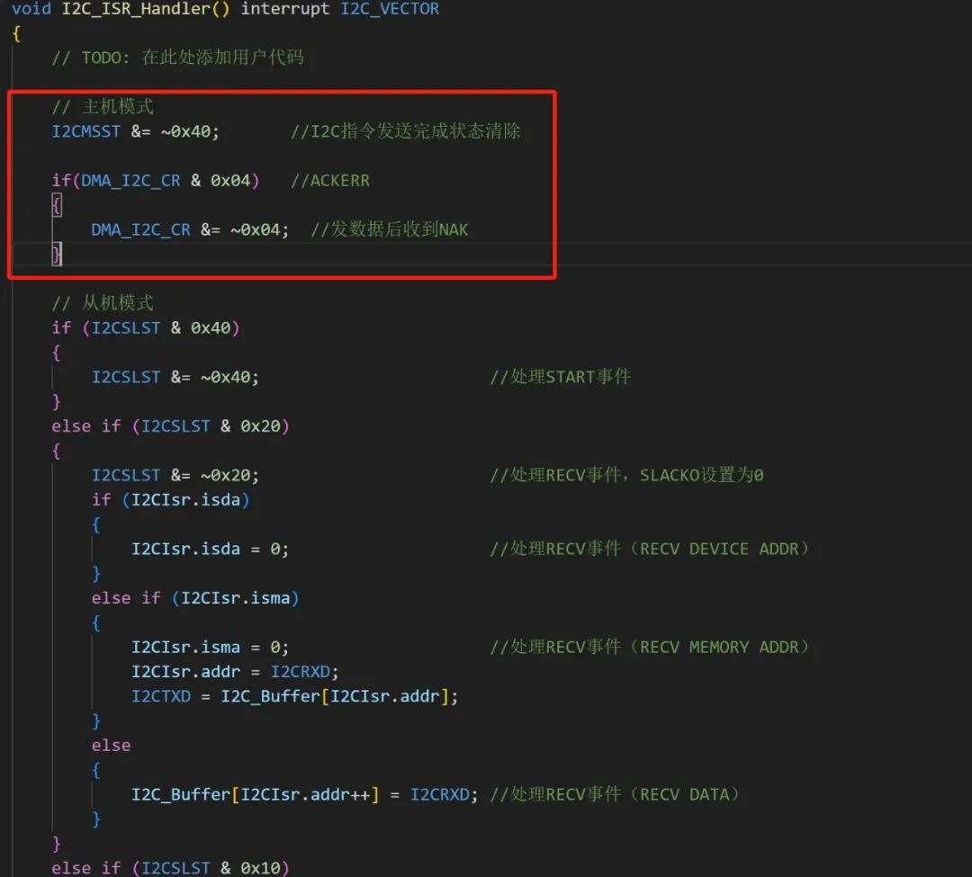
Now let’s look at how to send and receive data using IIC in the STC library functions (ignore the garbled text; it seems the official example code uses GB2312 encoding).
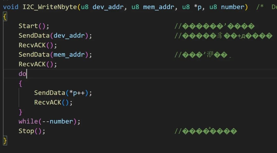
From the function names, it should be clear what they do.
First, send the start bit, then send the slave address, receive the ACK response, and send the register address. Problems start here, as the SGP30 sends a register address (command) that is 16 bits in two bytes.
However, we have a solution: we can place the second byte of the SGP30 command into the data to be sent, and the effect will be the same.
So we can still send data to SGP30.
But a bigger problem arises when receiving data.
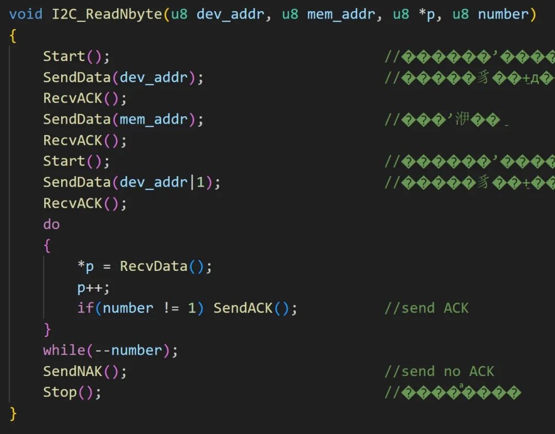
At first glance, there seems to be no problem with the receiving function, but the issue is that the SGP30 is different; its commands and register addresses are both 16 bits. So, can we not use the official library functions for SGP30…?
Let’s take a closer look at the functions Start, RecvACK, SendData; aren’t they just the IIC timing?
At worst, we can avoid using the library functions that integrate the complete process and piece together the timing ourselves.
Since these timings are not declared in the header file, we can declare them in the header file or directly encapsulate the SGP30 operations in the IIC file.
Clearly, the latter is better because the names of these timings are too simple and crude, and declaring them in the header file could easily lead to redefinition conflicts with external functions. So instead of bringing them ‘outside’, it’s better to go ‘inside’.
I have already written the functions; just copy the functions below into STC32G_I2C.c. Remember to declare them in the header file.
void Sgp30_Init(void){ Start(); SendData(0xB0); RecvACK(); SendData(0x20); RecvACK(); SendData(0x03); RecvACK(); Stop(); delay_ms(10);}void Sgp30_GetVal(uint8* val){ Start(); SendData(0xB0); RecvACK(); SendData(0x20); RecvACK(); SendData(0x08); RecvACK(); delay_ms(10); // Wait 10ms for safety Start(); SendData(0xB1); RecvACK(); val[0] = RecvData(); SendACK(); val[1] = RecvData(); SendACK(); val[2] = RecvData(); SendACK(); val[3] = RecvData(); SendACK(); val[4] = RecvData(); SendACK(); val[5] = RecvData(); SendNAK(); // Send no ACK Stop(); }Then, if we are in master mode, we basically won’t use interrupt functions.
Based on my practical tests, it works without enabling interrupts, so we can proceed without interrupts.
After configuring IIC and setting up the corresponding GPIO, we can use it.
#include "STC32G_GPIO.h"#include "STC32G_Delay.h"#include "STC32G_I2C.h"#include "STC32G_UART.h"#include "STC32G_NVIC.h"#include "STC32G_Switch.h"void GPIO_Init(void){ P0_MODE_OUT_PP(GPIO_Pin_1); P0_MODE_IN_HIZ(GPIO_Pin_0); P2_MODE_IO_PU(GPIO_Pin_4); P2_MODE_IO_PU(GPIO_Pin_5);}void UART_Init(void){ COMx_InitDefine initer; initer.BaudRateDouble = DISABLE; initer.Morecommunicate = DISABLE; initer.UART_BaudRate = 115200; initer.UART_BRT_Use = BRT_Timer3; initer.UART_Mode = UART_8bit_BRTx; initer.UART_RxEnable = ENABLE; UART_Configuration(UART3, &initer); NVIC_UART3_Init(ENABLE, Priority_1); UART3_SW(UART3_SW_P00_P01);}void IIC_Init(void){ I2C_InitTypeDef initer; initer.I2C_Enable = ENABLE; // Enable initer.I2C_Mode = I2C_Mode_Master; // Master mode initer.I2C_MS_WDTA = DISABLE; // Automatic sending initer.I2C_Speed = 58; // Set IIC speed to 100k I2C_Init(&initer); // NVIC_I2C_Init(I2C_Mode_Master,ENABLE,Priority_0); // Master/slave mode, I2C_Mode_Master, I2C_Mode_Slave; Enable interrupt, I2C_ESTAI/I2C_ERXI/I2C_ETXI/I2C_ESTOI/DISABLE; Priority (low to high) Priority_0,Priority_1,Priority_2,Priority_3 I2C_SW(I2C_P24_P25);}void main(void){ uint8 i = 0; uint8 Sgp30_ReceiveDate[6]; WTST = 0; // Set program instruction delay parameter, assign 0 to set the CPU execution instruction speed to the fastest EAXSFR(); // Enable extended SFR (XFR) access CKCON = 0; // Improve access speed to XRAM GPIO_Init(); UART_Init(); IIC_Init(); EA = 1; Sgp30_Init(); printf("Hello\r\n"); while(1){ Sgp30_GetVal(Sgp30_ReceiveDate); printf("%#x %#x %#x\t%#x %#x %#x\r\n",Sgp30_ReceiveDate[0], Sgp30_ReceiveDate[1],\ Sgp30_ReceiveDate[2], Sgp30_ReceiveDate[3], Sgp30_ReceiveDate[4], Sgp30_ReceiveDate[5]); delay_ms(3000); } return ;}Initially, the SGP30 data is fixed at CO2 400 and TVOC 0, and after waiting about ten to twenty seconds, the data becomes normal.
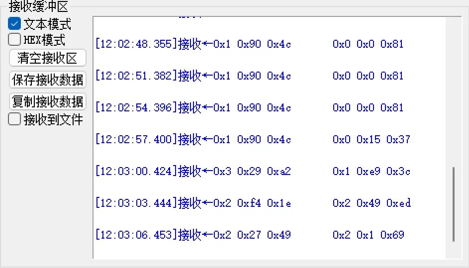
Generally, the concentration of CO2 will be between 400~1000ppm, which is normal.