Danfoss FC51 Series Modbus Communication Case Study
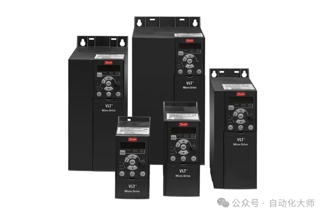
The Danfoss FC51 series is equipped with an RS485 interface, supporting Modbus RTU format communication. Today, I will introduce the communication setup instructions for this series of frequency converters and some communication cases with common devices.
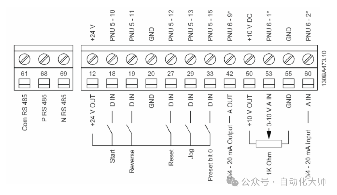
Wiring
- 68 Connect to RS485-
- 69 Connect to RS485+
Other connections depend on the actual control method and given method, which will not be discussed here.
FC Series Frequency Converter Parameter Settings
| Parameter Address | Set Value | Parameter Name | Description |
|---|---|---|---|
| 8-30 | 2 | Communication Protocol | Use MODBUS protocol |
| 8-31 | 1 | Communication Slave Address | Device slave address (1~247) |
| 8-32 | 2 | Communication Baud Rate | 9600 bps (set value correspondence needs to refer to the manual) |
| 8-33 | 0 | Communication Data Format | 8 data bits, even parity (E), 1 stop bit |
| 3-02 | * | Frequency Reference Value (MIN) | Minimum frequency setting value (unit: Hz/needs to be configured according to actual conditions) |
| 3-03 | * | Frequency Reference Value (MAX) | Maximum frequency setting value (unit: Hz/needs to be configured according to actual conditions) |
Danfoss Frequency Converter MODBUS Address Calculation Rules
The MODBUS address for Danfoss frequency converter communication must be calculated according to a specific rule: Parameter Number × 10 – 1 (decimal).
Example Analysis: If you need to read the frequency of the frequency converter, the corresponding parameter is 3-10 (which needs to be combined to calculate 310), then: MODBUS address = (310 × 10) – 1 = 3099. Some PLCs (such as Siemens) may require an address offset of one position, so the address would be 43100 (4 indicates function code).
FC Series Frequency Converter Control Word Details
| Bit | Value 0 | Value 1 | Bit | Value 0 | Value 1 |
|---|---|---|---|---|---|
| 00 | Reference Value | External Select Low Bit | 32 | Control Not Ready | Control Ready |
| 01 | Reference Value | External Select High Bit | 33 | Frequency Converter Not Ready | Frequency Converter Ready |
| 02 | DC Braking | No DC Braking | 34 | Inertia Stop | Safety Function Off |
| 03 | Inertia Parking | No Inertia Parking | 35 | No Alarm | Alarm |
| 04 | Fast Stop | No Fast Stop | 36 | Not Used | — |
| 05 | Lock Output | No Locked Frequency | 37 | Not Used | — |
| 06 | Acceleration/Deceleration Stop | Start | 38 | No Warning | Warning |
| 07 | No Function | Reset | 39 | Not Below Reference Value | Below Reference Value |
| 08 | No Function | Jog | 40 | Manual Mode | Automatic Mode |
| 09 | Acceleration 1 | Acceleration 2 | 41 | Out of Frequency Range | Running Within Frequency Range |
| 10 | Data Invalid | Data Valid | 42 | Stopped | Running |
| 11 | Close Relay 1 | Open Relay 1 | 43 | Not Used | — |
| 12 | Close Relay 2 | Open Relay 2 | 44 | Not Used | — |
| 13 | Parameter Setting | Select Low Bit | 45 | No Voltage Warning | Voltage Warning |
| 14 | Parameter Setting | Select High Bit | 46 | Not Within Current Limit | Current Limit |
| 15 | No Reverse | Reverse | 47 | No Overheat Warning | Overheat Warning |
| 16-31 | Reference Value 0-FFFFF (-200%~200%) | — (Reserved or Undefined) | 48-63 | Open Loop Mode: Frequency Converter Output Frequency | Closed Loop Mode: Frequency Converter Feedback Signal |
| 65 | Write Parameters to Converter’s RAM | Write Parameters to Converter’s RAM and EEPROM |
Siemens S7-200 and FC51 MODBUS RTU Communication Instructions
MODBUS RTU communication requires the master station to send specific formatted hexadecimal codes, and the slave responds to establish communication. This example illustrates the MODBUS RTU communication process of the DANFOSS frequency converter with a PLC master station and a frequency converter slave with an address of 1. Programmers can flexibly adapt based on different communication situations.
1. Start Frequency Converter (Forward)
Command Code: 01 0f 00 00 00 20 04 7c 04 33 13 C9 E4 Description: Start the frequency converter in the forward direction, frequency 15 Hz, control word and frequency setting need to swap the high and low 8 bits.
2. Start Frequency Converter (Reverse)
Command Code: 01 0f 00 00 00 20 04 7c 84 33 13 C8 0C Description: Start the frequency converter in the reverse direction, frequency 15 Hz, control word and frequency setting need to swap the high and low 8 bits. Given value calculation: ==(H1333/H4000)*50HZ = 15HZ
3. Read Frequency Command
Command Code: 01 01 00 20 00 20 3c 18 Return Code: 09 01 01 04 07 0F D9 19 50 FC Status Word: 0F07 Frequency Value: 19D9 CRC: (01 01 04 07 0F D9 19)=50 FC Description: The read 16-bit frequency value needs to swap the high and low 8 bits to get the actual value.
4. Communication Given Frequency Value Conversion Calculation Method
H4000 (i.e., 16384) corresponds to 100% and 50HZ.
5. Frequency Converter Given Frequency Value Description
The frequency converter given frequency value is the sum of parameters 3-15, 3-16, and 3-17. If all three parameters are selected for the bus, the actual given value is three times.