
In the ADAS development community, no engineer can bypass the “standardization hurdle” of AUTOSAR. Especially its C language vehicle motion control interface, which serves as a “critical bridge” between ADAS algorithms and vehicle actuators. Many people write interfaces according to the specifications, yet encounter numerous issues during execution: data anomalies, slow response to control commands, and compatibility errors when switching ECUs, leading to significant frustration!
1. First Understand: The Underlying Architecture Logic, Don’t Just Dive into Coding
Many people stumble during implementation because they fail to grasp the underlying logic and jump straight into coding the interface. The four-layer VMC architecture designed by AUTOSAR for ADAS motion control has a core principle: “Do not mix layers arbitrarily, andfollow the interface rules” to avoid system chaos.
This four-layer architecture has clearly defined roles from top to bottom, easily understood with a diagram:
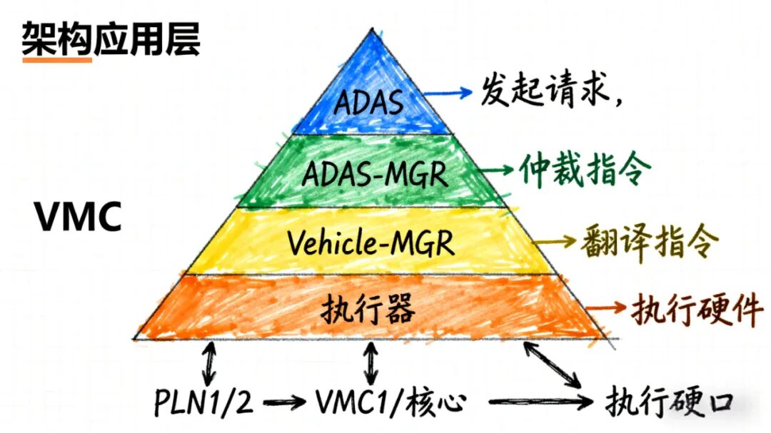
(Diagram Explanation: A pyramid structure with different colors for each layer – ADAS Application Layer (blue), ADAS-MGR Layer (green), Vehicle-MGR Layer (yellow), Actuator Layer (orange). Arrows indicate interfaces like PLN1/2, VMC1/2, with notes like “Initiate Request” and “Arbitrate Command” for clarity on data flow.)
• ADAS Application Layer: This includes the functional modules we commonly develop, such as ACC, AEB, and LKA, acting as the “request initiator” responsible for issuing control requests;
• ADAS-MGR Layer: Functions like a “referee“, receiving requests from multiple application layers, such as ACC wanting to accelerate and AEB needing to brake. It must determine priority and consolidate a unified command;
• Vehicle-MGR Layer: Acts as a “translator“, converting the “referee’s” abstract commands into specific parameters that the actuators can understand;
• Actuator Layer: This consists of the vehicle’s hardware for power, braking, and steering, which is responsible for executing the commands.
Communication between layers relies entirely on standardized interfaces, such as the PLN1/2 interface between the application layer and the “referee”, the VMC1/2 interface between the “referee” and the “translator”, and the ACL1/2 (power), BRK1/2 (braking), STR1/2 (steering) interfaces between the “translator” and the hardware. The parameter definitions, data types, and transmission protocols for these interfaces are clearly outlined in the AUTOSAR specifications, which should be followed during implementation to avoid compatibility issues.
2. Key Implementation: Three Core Interfaces, Don’t Miss These Details
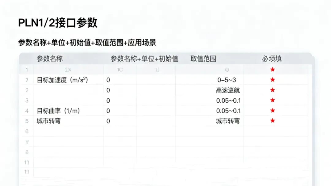
In actual development, the three core interface scenarios are the most prone to issues. Based on specific project requirements, here are the practical points derived from real experience:
1. PLN1/2 Interface: The “Demand Transmission” between the Application Layer and the “Referee”
This interface serves as the channel for the application layer to send requests to the “referee”. For example, if ACC wants to accelerate, it must transmit the “target acceleration” through this interface, and if LKA needs to turn, it sends the “target curvature”. Two key points to focus on during implementation:
First, do not set parameters arbitrarily. According to AUTOSAR specifications, the unit for target acceleration is m/s², the initial value must be set to 0, and the range should align with vehicle performance (generally -5 to 3 m/s², where negative indicates deceleration); the unit for target curvature is 1/m, and the initial value should also be 0, with a typical setting of 0.05 to 0.1 1/m for urban road turns. Previously, a colleague mixed up the units, resulting in the “referee” not recognizing the request, causing the system to throw an error after a lot of effort.
Second, handle “demand conflicts”. For instance, if ACC wants to accelerate (target acceleration 2 m/s²) while AEB detects a collision and needs to brake (target acceleration -4 m/s²), the interface must include a priority identifier so the “referee” knows whose command to follow (typically, AEB has a higher priority than ACC). Ensure to add a priority field in the interface; otherwise, conflicting commands will lead to system chaos.
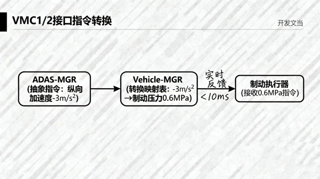
2. VMC1/2 Interface: The “Command Handover” between the “Referee” and the “Translator”
This interface is responsible for transmitting the unified command consolidated by the “referee”, serving as the key link between algorithms and hardware. Focus on “command translation” and “status feedback” during implementation:
Regarding “command translation”, the “referee” issues abstract targets, such as “longitudinal acceleration -3 m/s²”, which the “translator” must convert into a comprehensible “braking pressure 0.6 MPa” for the braking system. During implementation, create a “conversion mapping table” in the interface to correlate different accelerations to specific braking pressures and different curvatures to steering angles, ensuring precise command transmission.

“Status feedback” is also crucial; the “translator” must inform the “referee” through reverse interfaces whether the hardware has received the command, how well it is executing, and if there are any faults. Ensure that feedback latency does not exceed a certain threshold; otherwise, the “referee” cannot adjust commands in time, potentially leading to issues like delayed braking or insufficient steering.
3. ACL1/2/BRK1/2/STR1/2 Interfaces: The “Last Mile” between the “Translator” and Hardware
This set of interfaces directly interacts with the hardware and is most susceptible to compatibility issues. The core focus should be on “protocol matching” and “fault backup”:
On “protocol matching”, different brands of hardware (e.g., Bosch braking, ZF steering) may support different communication protocols (CAN FD, Ethernet), while AUTOSAR specifications prioritize CAN FD. During implementation, ensure protocol conversion in the “translator” to align the interface protocol with the hardware, and test data transmission stability to avoid packet loss or errors; otherwise, incorrect steering angles could lead to LKA functionality deviating.
“Fault backup” is also essential; for instance, if the steering control STR1 interface fails, it must switch to the backup STR2 interface within 0.3 seconds while also reporting the fault status. Design fault identification and switching logic in the interface to prevent a single interface failure from crippling the entire function.
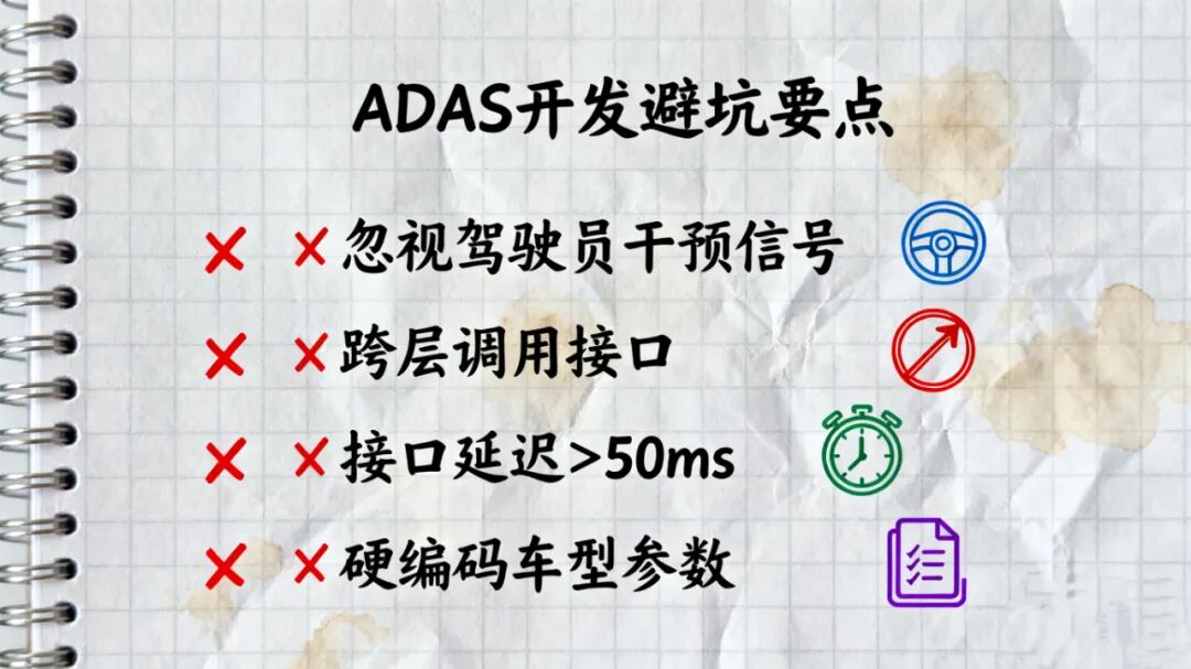
3. Pitfall Guide: Avoid These 4 Common Mistakes!
In addition to the interfaces themselves, avoid these four pitfalls during implementation, which are hard-earned lessons from experienced developers:
1. Do not overlook the “driver intervention signal”. If the driver applies the brakes or turns the steering wheel, the hardware must promptly relay this feedback to the system, causing the ADAS function to pause (e.g., ACC disengagement). In a previous project, this signal field was not designed, leading the system to “ignore” driver actions, nearly resulting in a safety risk.
2. Never cross-layer call interfaces. Some people, for convenience, allow the application layer to directly call the braking interface…
Content Source: Internet
Editor for this issue: Xiao Ai
Paper Submission: As a leading high-tech advanced manufacturing technology service platform, AMT accepts academic paper submissions; the publication of manuscripts is entirely non-profit and free of charge; paper submission email: [email protected]
Copyright Statement: AMT respects copyright and appreciates the hard work and creativity of every author; except for works that cannot be traced, we have noted the source at the end of the article; if any articles, videos, images, or texts involve copyright, please contact us immediately with proof, and we will confirm the copyright and delete the content or pay remuneration according to national standards!