01
Overview
1.1 What is I2C?
I2C (Inter-Integrated Circuit) is a serial communication protocol developed by Philips, which uses a two-wire system (SDA and SCL) to facilitate data transmission between devices.
1.2 Where does I2C come from?
The I2C bus was introduced by Philips in the early 1980s as a serial, half-duplex bus primarily used for communication between chips over short distances and at low speeds. The I2C bus consists of two bidirectional signal lines: one data line (SDA) for sending and receiving data, and one clock line (SCL) for synchronizing the clocks of the communicating parties. The hardware structure of the I2C bus is simple, which simplifies PCB routing, reduces system costs, and improves system reliability, leading to its widespread application across various fields.
1.3 What are the characteristics of I2C?
- Half-duplex communication: Multiple master and slave devices can coexist on the same bus, with the master responsible for read/write operations and the slave only responding to commands from the master.
- Low power consumption: Only two wires are needed, and the open-drain output design reduces power consumption, with a maximum data transmission rate of 100 kbps.
- Multi-master mode: Supports multiple master devices controlling the bus simultaneously, suitable for complex systems.
02
API Documentation
2.1 Class Definition
- ESP32 supports two modes of I2C usage: hardware I2C and software emulated I2C. Hardware I2C should be prioritized, and if there are too many I2C devices and not enough pins, software emulated I2C can be used, although it will be slightly slower.
- ESP32 has two hardware I2C buses, numbered 0 and 1.
<span><span><span>I2C(0)</span></span></span>indicates the use of I2C bus 0. <span><span><span>scl</span></span></span>and<span><span><span>sda</span></span></span>parameters are used to specify the pins for the clock line and data line.<span><span><span>freq</span></span></span>is the communication frequency, where 400000 indicates 400 kHz (fast mode).- Software emulated I2C cannot use arbitrary pins; pins 2 and 4 cannot be used, while pins 14 and 15 have been tested and can be used.
import machine
# Using hardware I2C
i2c = machine.I2C(0, sda=21, scl=22)
# Using software emulated I2C
i2c = machine.SoftI2C(sda=Pin(14), scl=Pin(15), freq=100000)
2.2 Initialization
-
Initialize to construct the I2C bus.
i2c.init(scl=Pin(5), sda=Pin(4), freq=100000)2.3 Scan Devices
-
Scan for I2C addresses and return the list of devices.
devices = i2c.scan()
if len(devices) == 0:
    print("No I2C devices found!")
else:
    print("I2C devices found at addresses:", [hex(addr) for addr in devices])
2.4 Start
-
Trigger the START condition on the bus (SDA goes low when SCL is high).
i2c.start()2.5 Stop
-
Trigger the STOP condition on the bus (SDA goes high when SCL is high).
i2c.stop()2.6 Write Data
- When using the write() function, it must be used with the start function; otherwise, the number of bytes written cannot be returned.
- Write a byte array to the device at address 0x3C.
<span><span><span>writeto(addr, buf)</span></span></span>function writes the data in<span><span><span>buf</span></span></span>to the device at the specified address.
buf = b'123'
i2c.start()
i2c.write(buf)

i2c.writeto(0x3C, b'\x00\x01\x02')
2.7 Read Data
-
Read 6 bytes from the device at address 0x68.
<span><span><span>readfrom(addr, nbytes)</span></span></span>function reads<span><span><span>nbytes</span></span></span>bytes of data from the device at the specified address.
data = i2c.readfrom(0x68, 6)2.8 Read Register
- Write a byte (0x00) to register 0x6B of the device at address 0x68.
- Read 6 bytes starting from register 0x3B of the device at address 0x68. An error will occur if less than 6 bytes are read.
i2c.writeto_mem(0x68, 0x6B, b'\x00')
time.sleep_ms(100)

data = i2c.readfrom_mem(0x68, 0x3B, 6)
print("Register data:", data)
03
Project Practice
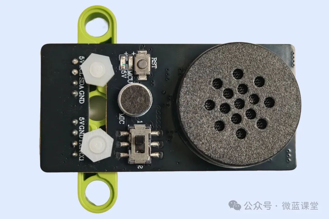
Program Explanation
This is also a voice recognition module that uses I2C communication. The device address is 0x2B, and the register for reading data is 0x64. After initialization, it continuously listens for data, and when I say a voice command, the voice recognition module can recognize it, and a recognition symbol will be printed.
import machine
import time
from micropython import const


class VoiceI2c:
    _address: int = const(0x2b)

    def __init__(self):
        self._i2c = machine.SoftI2C(scl=machine.Pin(15), sda=machine.Pin(14), freq=100000)


        devices = self._i2c.scan()
        if len(devices) == 0:
            print("No I2C devices found!")
        else:
            print("I2C devices found at addresses:", [hex(addr) for addr in devices])

    @property
    def values(self):
        data = self._i2c.readfrom_mem(self._address, 0x64, 1)
        return int.from_bytes(data, 'little')


voice = VoiceI2c()

while True:
    data = voice.values
    print(data)
    time.sleep(0.2)
For those who need accessories, you can purchase them from my Taobao store under the same name.
 Follow me for more sharing|Weilan Classroom