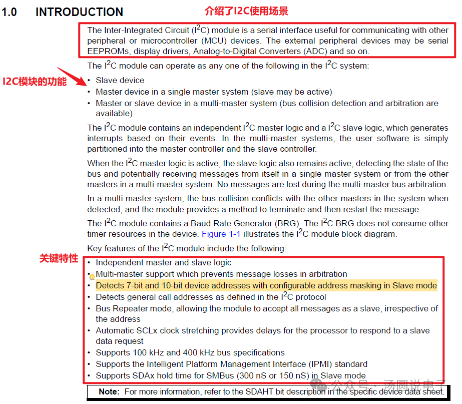
Functionality: Use interrupts to send data, efficiently utilizing the I2C peripheral.First, refer to the manual’s I2C section to understand the basic functions and usage of I2C. Then choose the appropriate operational method based on the functionality you want to implement.Obtaining information about OLED: Search for “0.96 inch OLED screen” on Taobao, where you can find the data download link in the detailed description.Refer to the I2C section in the chip manualThe beginning introduces the communication steps between a single I2C Master and Slave.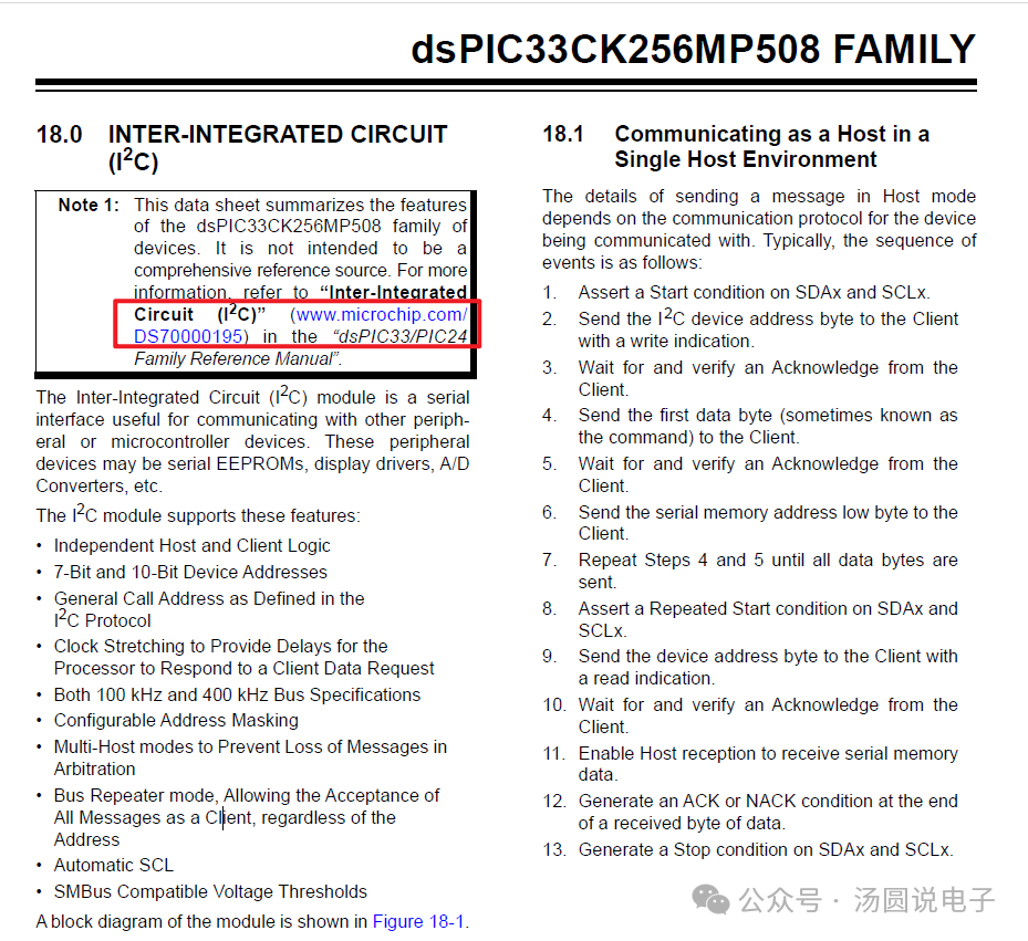 Download and view the I2C reference document as suggested in the manual.
 Since we need to use the interrupt method of I2C to send data, we need to check what interrupts the I2C master has, how they are triggered, etc.
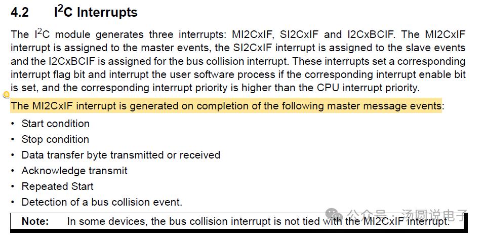 From the above documents, we can see that: start signal, stop signal, data transmission/reception complete, ACK signal interrupt, repeated start signal, and bus busy interrupt will trigger the I2C master interrupt MI2CxIF.About I2C Slave AddressThe Masterneeds to left shift the address bits<7:0>, the last bit of the address is used to indicate the direction of data transmission: read or write. 0: represents write, 1: represents read.
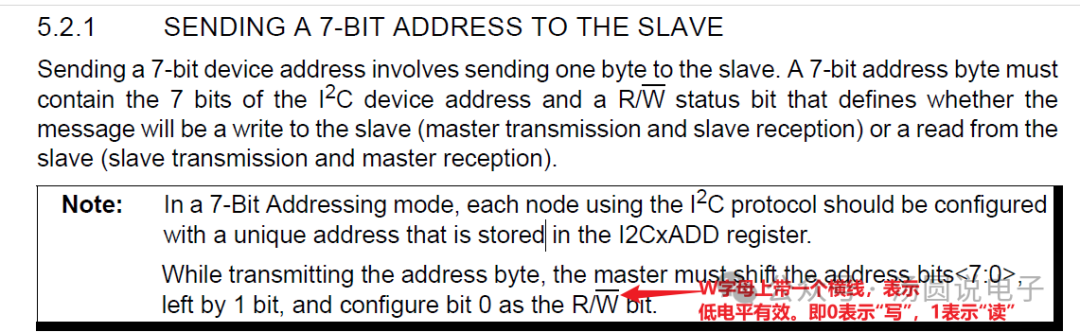 Here we need to use I2C to operate the OLED screen to display data, so the MCU acts as the I2C master and the OLED screen as the I2C slave. By consulting the example program of the OLED screen, we know that its I2C slave address is 0x3C.Why is the OLED screen address 0x3C instead of 0x78?Because the I2C master operates the I2C slave address after it has been left-shifted by one bit (the last bit is the read/write flag), so0x3Cleft-shifted1bit becomes0x78, and then0x78is assigned toI2CxTRNregisterso that the finaladdress sent on the I2C bus is0x3C.The first byte of data sent after the I2C start signal is the address.Refer to the I2C reference manual for the usage of “Single Master”.Since we only have one I2C Master (dsPIC33CK microcontroller) and one I2C Slave (OLED screen), it perfectly fits this situation.
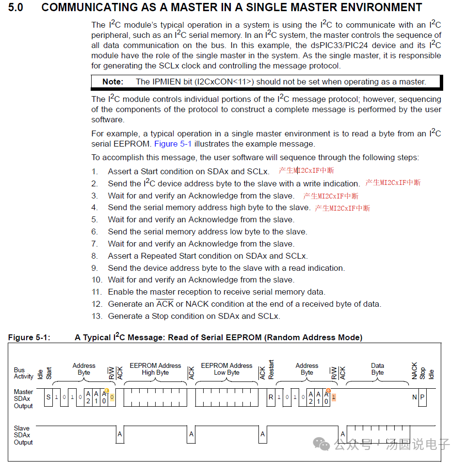 Since we are operating the I2C interface with the OLED screen, which does not have a read function, our operation steps are not as extensive as those for the EEPROM mentioned above. The I2C operation for the OLED screen is as follows:0. Initialize the I2C pins, this step is already completed by the code generated by MCC.1. Send I2C start signal2. Send OLED screen I2C slave address3. Wait for the ACK sent by the OLED screen slave4. Send data/command to the OLED screen5. Wait for the ACK sent by the OLED screen slave6. Send I2C stop signal
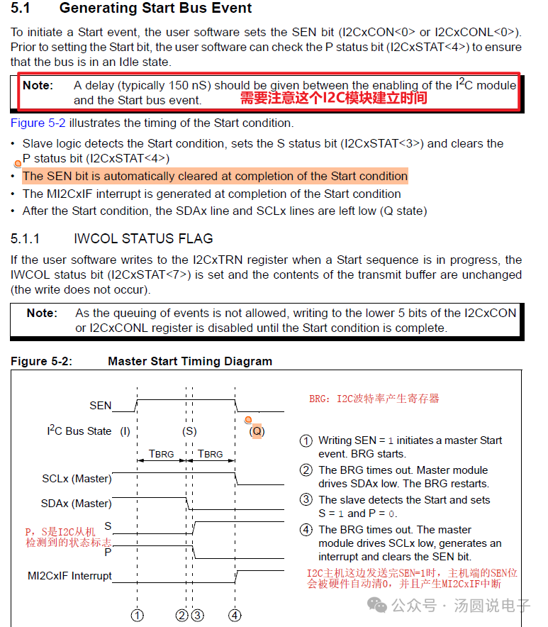
Method to generate I2C start signal
Before generating the start signal, confirm that the I2C bus is idle; otherwise, the start signal will fail.
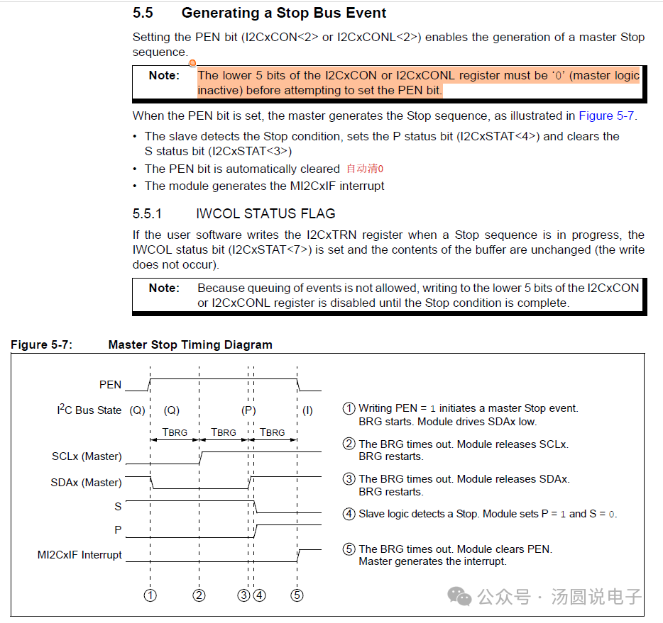
Method to generate I2C stop signal
Note the instructions in the Note box; before generating the stop signal, it is also necessary to confirm that the low 5 bits of the I2CxCON register are all 0 to produce a normal stop signal.
Refer to the “Design Tips” at the end of the document to write code that checks if the bus is idle.
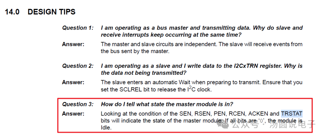
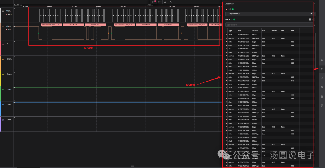
i2c_Mode_state = I2C2CONL & 0x1F;if((i2c_Mode_state || I2C2STATbits.TRSTAT) == 0) //I2C bus idle{// Send start signal I2C2CONLbits.SEN = 1; // Initiate start sequence}Code generation and writing
Configure the I2C peripheral in MCC
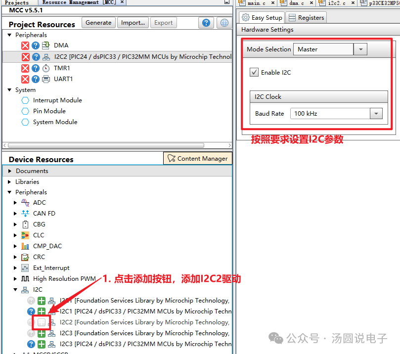 Enable I2C master interruptsNote: When disabling the I2C2 Master Event interrupt, MCC may pop up a warning that this interrupt cannot be disabled. In fact, this interrupt can be disabled; in the next article, we will disable this interrupt when using DMA + I2C to achieve more efficient transmission.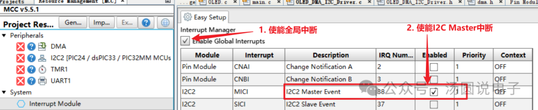
Modify the I2C master interrupt MI2CxIF service function, delete other codes, and add the following code. The I2C module will generate I2C master interrupts during the sending of start signals, stop signals, transmission completion, etc.
extern volatile uint8_t i2c_master_sta = 0;void __attribute__ ( ( interrupt, no_auto_psv ) ) _MI2C2Interrupt ( void ){ IFS2bits.MI2C2IF = 0; // Clear I2C master interrupt flag i2c_master_sta++; // Interrupt judgment}Add the following code to the main function of the main program
uint8_t oled_initCmd[]={0x78,0x00,0xAE, 0x78,0x00,0x20, 0x78,0x00,0x10, 0x78,0x00,0xb0, 0x78,0x00,0xc8, 0x78,0x00,0x00, 0x78,0x00,0x10, 0x78,0x00,0x40, 0x78,0x00,0x81, 0x78,0x00,0xdf, 0x78,0x00,0xa1, 0x78,0x00,0xa6,0x78,0x00,0xa8, 0x78,0x00,0x3F, 0x78,0x00,0xa4, 0x78,0x00,0xd3, 0x78,0x00,0x00, 0x78,0x00,0xd5,0x78,0x00,0xf0, 0x78,0x00,0xd9, 0x78,0x00,0x22, 0x78,0x00,0xda, 0x78,0x00,0x12, 0x78,0x00,0xdb, 0x78,0x00,0x20, 0x78,0x00,0x8d, 0x78,0x00,0x14, 0x78,0x00,0xaf};volatile uint8_t i2c_master_sta = 0;void Test_I2C_Master_Write(uint8_t data_len){ uint8_t i2c_Mode_state = 0; static uint8_t i = 0; if(i < data_len) { switch(i2c_master_sta) { case START_I2C: i2c_Mode_state = I2C2CONL & 0x1F; if((i2c_Mode_state || I2C2STATbits.TRSTAT) == 0) // I2C bus idle { I2C2CONLbits.SEN = 1; // Initiate start sequence } break; case DEVICE_ADDRESS_I2C: I2C2TRN = oled_initCmd[i]; break; case CMD_OLED_I2C: I2C2TRN = oled_initCmd[i+1]; break; case DATA_OLED_I2C: I2C2TRN = oled_initCmd[i+2]; break; case STOP_I2C: i2c_Mode_state = I2C2CONL & 0x1F; if(i2c_Mode_state == 0) // I2C bus idle { I2C2CONLbits.PEN = 1; // Initiate start sequence } break; case IDEL_I2C: default: i2c_master_sta = 0; i = i + 3; break; } } }int main(void){ SYSTEM_Initialize(); i2c_master_sta = 0; while (1) { // Add your application code Test_I2C_Master_Write(sizeof(oled_initCmd) / sizeof(oled_initCmd[0])); } return 1; }Use a logic analyzer on Logic 2 software to view the waveform and data of the above I2C channel.