Communication between electronic devices is like communication between humans, as both parties need to speak the same language. In electronic products, these languages are called communication protocols.
Previously, I shared separate articles on SPI, UART, and I2C communication; this article compares them.
Serial vs Parallel
Electronic devices communicate by sending data bits. A bit is binary, and can only be 1 or 0. Through rapid changes in voltage, bits are transmitted from one device to another. In a 5V system, “0” is communicated through a short pulse of 0V, while “1” is communicated through a short pulse of 5V.
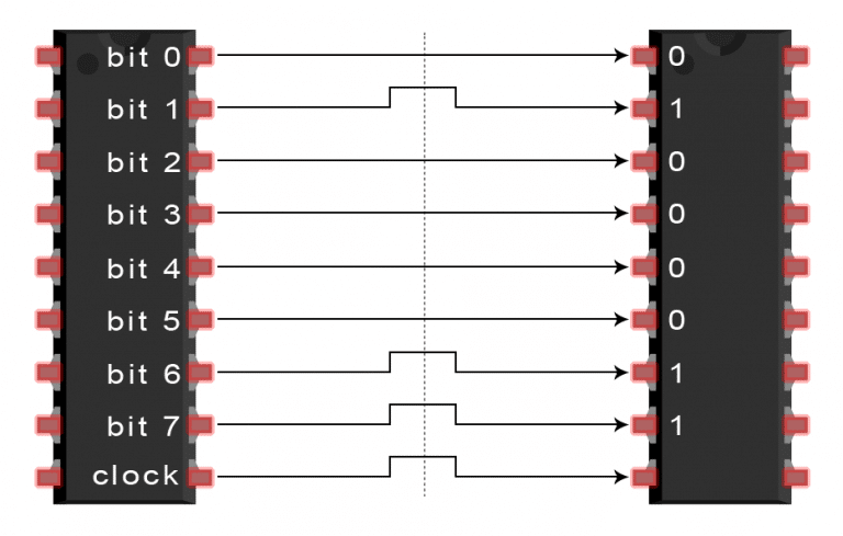
Data bits can be transmitted in either parallel or serial form. Additionally, you can learn more through this video: Video explaining UART, I2C, SPI serial communication。In parallel communication, data bits are transmitted simultaneously on multiple lines. The image below shows the parallel transmission of the letter “C” in binary (01000011):
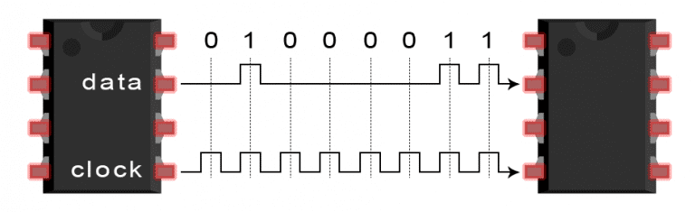
In serial communication, bits are sent one by one over a single wire. The image below shows the serial transmission of the letter “C” in binary (01000011):
SPI Communication
SPI is a common universal communication protocol for devices. Its unique advantage is that it can transmit data without interruption, allowing for the continuous sending or receiving of any number of bits. In contrast, I2C and UART send data in packets with a limited number of bits.
In SPI devices, the devices are divided into master and slave systems. The master is the controlling device (usually a microcontroller), while the slave (usually a sensor, display, or storage chip) receives instructions from the master.
An SPI communication setup includes four signal lines:MOSI (Master Output/Slave Input) – signal line, master outputs, slave inputs.MISO (Master Input/Slave Output) – signal line, master inputs, slave outputs.SCLK (Clock) – clock signal.SS/CS (Slave Select/Chip Select) – chip select signal.
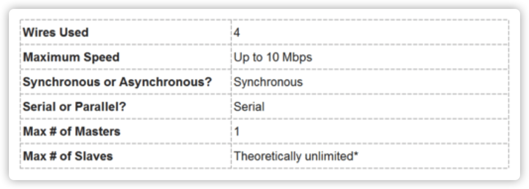
Features of SPI Protocol
In fact, the number of slaves is limited by the system load capacitance, which reduces the master’s ability to switch accurately between voltage levels.
Clock Signal
One bit of data is transmitted per clock cycle, so the speed of data transmission depends on the frequency of the clock signal. The clock signal is generated by the master, so SPI communication is always initiated by the master.
Any communication protocol that shares a clock signal is called synchronous. SPI is a synchronous communication protocol, while some asynchronous communications do not use a clock signal. For example, in UART communication, both parties are set to a pre-configured baud rate, which determines the speed and timing of data transmission.
Chip Select Signal
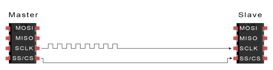
The master enables communication by pulling down the CS/SS of the slave. In idle/non-transmission state, the chip select line remains high. The master can have multiple CS/SS pins, allowing it to communicate with multiple different slaves.
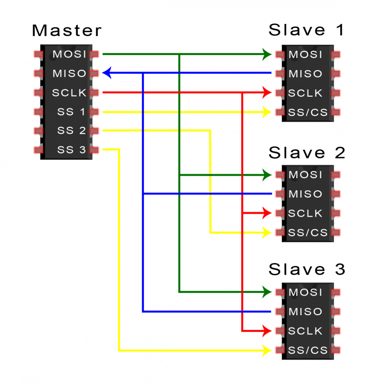
If the master has only one chip select pin available, it can connect these slave devices in the following way:
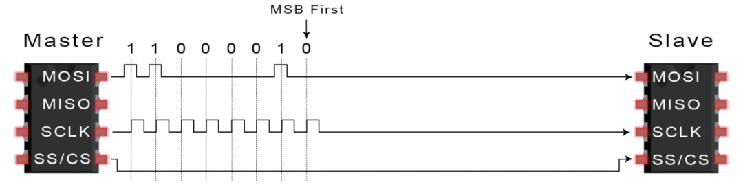
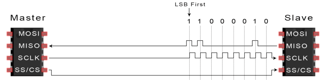
MOSI and MISO The master sends data to the slave via MOSI in a serial manner, and the slave can also send data to the master via MISO, allowing both to occur simultaneously. Thus, theoretically,SPI is a full-duplex communication protocol.
Transmission Steps
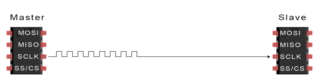
1. The master outputs the clock signal
2. The master pulls down the SS/CS pin to activate the slave
3. The master sends data to the slave via MOSI
4. If a response is needed, the slave returns data to the master via MISO
Using SPI has some advantages and disadvantages, and if you are choosing between different communication protocols, you should fully consider the project requirements.
Advantages of SPI
SPI communication has no start or stop bits, allowing for continuous data flow without interruption; it does not have a complex slave addressing system like I2C, and the data transfer rate is higher than I2C (almost twice as fast). Independent MISO and MOSI lines can send and receive data simultaneously.
Disadvantages of SPI
SPI uses four lines (I2C and UART use two lines), has no acknowledgment of successful signal reception (I2C has this feature), and does not have any form of error checking (such as parity bits in UART).
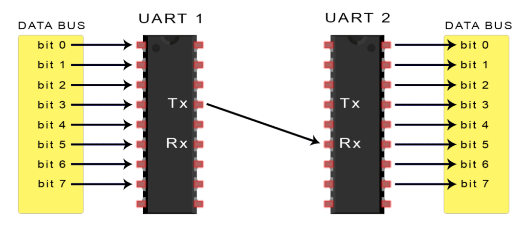
UART stands for Universal Asynchronous Receiver/Transmitter, also known as serial communication; it is not a communication protocol like SPI and I2C, but rather a physical circuit in a microcontroller or a standalone IC.
The main purpose of UART is to send and receive serial data, and its best advantage is that it only uses two wires to transmit data between devices. The principle of UART is easy to understand, but if you haven’t read about SPI communication protocol, that may be a good starting point.
UART Communication
In UART communication, two UARTs communicate directly with each other. Related example: Pressing a button to send data through the serial port. The transmitting UART converts parallel data from a controlling device (like a CPU) into serial form and sends it to the receiving UART.Only two wires are needed to transmit data between two UARTs, with data flowing from the Tx pin of the transmitting UART to the Rx pin of the receiving UART: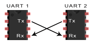 UART is asynchronous communication, meaning there is no clock signal; instead, start and stop bits are added to the data packets.These bits define the start and end of the packet, allowing the receiving UART to know when to read the data.When the receiving UART detects the start bit, it reads the bits in the data frame at a specific baud rate.The baud rate is a measure of data transmission speed, expressed in bits per second (bps). Both UARTs must operate at approximately the same baud rate, with the baud rate between transmitting and receiving UARTs differing by no more than about 10%.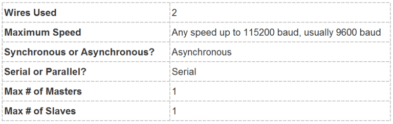
How UART Works
After the transmitting UART retrieves parallel data from the data bus, it adds a start bit, a parity bit, and a stop bit to form a data packet, which is then serially output bit by bit from the Tx pin, while the receiving UART reads the data packet bit by bit on its Rx pin. UART data consists of 1 start bit, 5 to 9 data bits (depending on the UART), an optional parity bit, and 1 or 2 stop bits: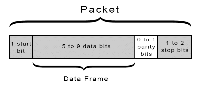
Start Bit:
The UART data transmission line typically remains at a high voltage level when not transmitting data.When transmission begins, the transmitting UART pulls the transmission line from high to low voltage within one clock cycle, and when the receiving UART detects the transition from high to low voltage, it begins to read the bits in the data frame at the baud rate.
Data Frame:
The data frame contains the actual data being transmitted.If a parity bit is used, it can be 5 bits long, up to a maximum of 8 bits.If no parity bit is used, the length of the data frame can be 9 bits.
Parity Bit:
The parity bit is a way for the receiving UART to determine if any data has changed during transmission.After the receiving UART reads the data frame, it counts the number of bits that are 1 and checks whether the total is even or odd, and whether it matches the data.
Stop Bit:
To signal the end of the data packet, the transmitting UART drives the data transmission line from low voltage to high voltage for at least two bit times.
Transmission Steps
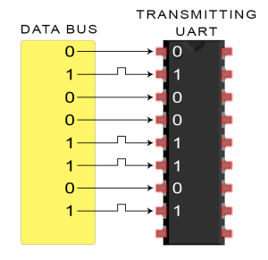
1. The transmitting UART receives parallel data from the data bus:
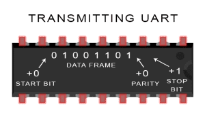
2. The transmitting UART adds the start bit, parity bit, and stop bit to the data frame:
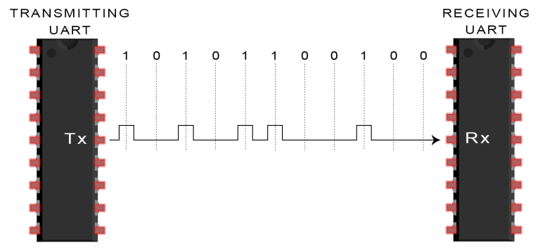
3. The entire data packet is serially sent from the transmitting UART to the receiving UART. The receiving UART samples the data line at the pre-configured baud rate:
4. The receiving UART discards the start bit, parity bit, and stop bit from the data frame:
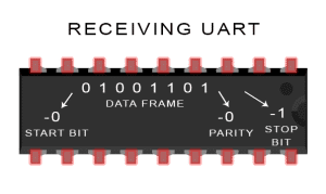
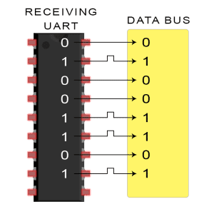
5. The receiving UART converts the serial data back into parallel data and transmits it to the data bus of the receiving end:
No communication protocol is perfect, but UART excels at its job.Below are some pros and cons to help you determine if they meet your project needs:
Advantages
-
Only uses two wires
-
No clock signal required
-
Parity bit for error checking
-
As long as both parties set up the structure of the data packet
-
A well-documented and widely used method
Disadvantages
-
Maximum data frame size is 9 bits
-
Does not support multiple slave systems or multiple master systems
-
The baud rate of each UART must be within 10% of each other
I2C Communication
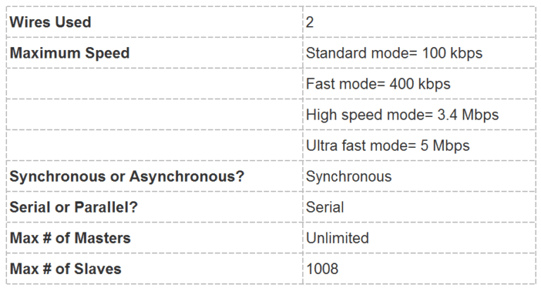
The I2C bus is a simple, bidirectional two-wire synchronous serial bus developed by Philips. Related article: Implementing IIC driver using C language in STM32 development. It only requires two wires to transmit information. It combines the advantages of SPI and UART, allowing multiple slaves to connect to a single master (like SPI), and also enables multiple masters to control one or more slaves.This is very useful when you want multiple microcontrollers to log data to a single storage card or display text on a single LCD.
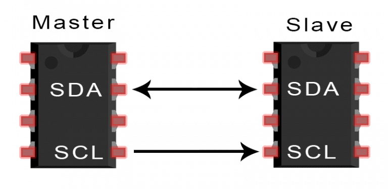
SDA (Serial Data) – data line.
SCL (Serial Clock) – clock line.
I2C is a serial communication protocol, so data is transmitted bit by bit along SDA. Like SPI, I2C also requires a clock synchronization signal, and the clock is always controlled by the master.
How It Works
The data transmission of I2C is done in the form of multiple msgs, with each msg containing the binary address frame of the slave, one or more data frames, as well as start and stop conditions, read/write bits, and ACK/NACK bits between the data frames:
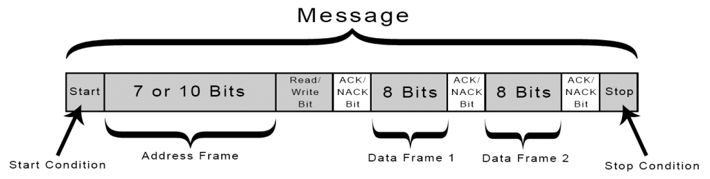
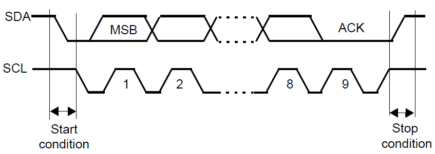
Start Condition: When SCL is high, SDA switches from high to low.
Stop Condition: When SCL is high, SDA switches from low to high.
Address Frame: A unique 7-bit or 10-bit sequence for each slave device used for address recognition between the master and slave devices.
Read/Write Bit: A single bit; if the master is sending data to the slave, it is low; if requesting data, it is high.
ACK/NACK: Each frame in the message is followed by an ACK/NACK bit. If the address frame or data frame is successfully received, the receiving device returns an ACK bit to indicate confirmation.
Addressing
Since I2C does not have a chip select line like SPI, it needs to use another method to confirm a particular slave device, which is addressing.
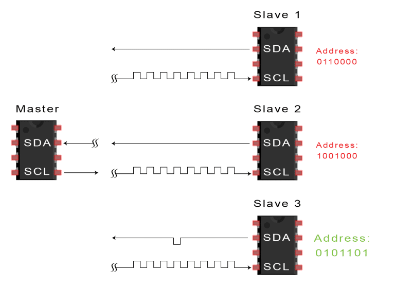
The master sends the address of the slave it wants to communicate with to each slave, and each slave compares it with its own address. If the address matches, it sends a low-level ACK bit back to the master. If it does not match, no action is taken, and the SDA line remains high.
Read/Write Bit
The end of the address frame contains a read/write bit. If the master is sending data to the slave, it is low. If the master is requesting data from the slave, it is high.
Data Frame
Once the master detects the ACK bit from the slave, it can send the first data frame. The data frame is always 8 bits long, and each data frame is immediately followed by an ACK/NACK bit to verify the reception status. After all data frames are sent, the master can send a stop condition to the slave to terminate communication.
Transmission Steps
1. When the SCL line is high, the master initiates bus communication by switching the SDA line from high to low.
2. The master sends the 7-bit or 10-bit address of the slave it wants to communicate with, along with the read/write bit:
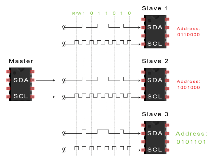
3. Each slave compares the address sent by the master with its own address. If the address matches, the slave returns an ACK bit by pulling the SDA line low. If the master’s address does not match the slave’s address, the slave pulls the SDA line high.
4. The master sends or receives data frames:
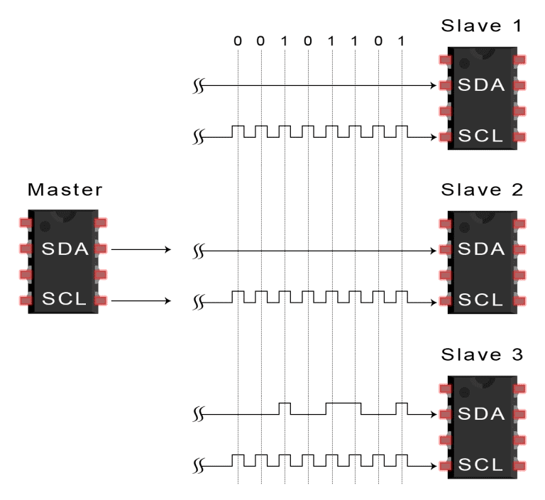
5. After each data frame is transmitted, the receiving device returns another ACK bit to the sender to confirm that the frame has been successfully received:
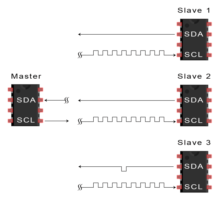
6. The master then switches the SCL to high and then switches the SDA to high to send the stop condition to the slave.
Single Master vs Multiple Slaves
Since I2C uses addressing, one master can control multiple slaves. Using a 7-bit address allows for a maximum of 128 (2^7) unique addresses. Using a 10-bit address is not common but can provide 1,024 (2^10) unique addresses.If you want to connect multiple slaves to a single master, use a 4.7K ohm pull-up resistor to connect them, for example, connecting the SDA and SCL lines to Vcc:
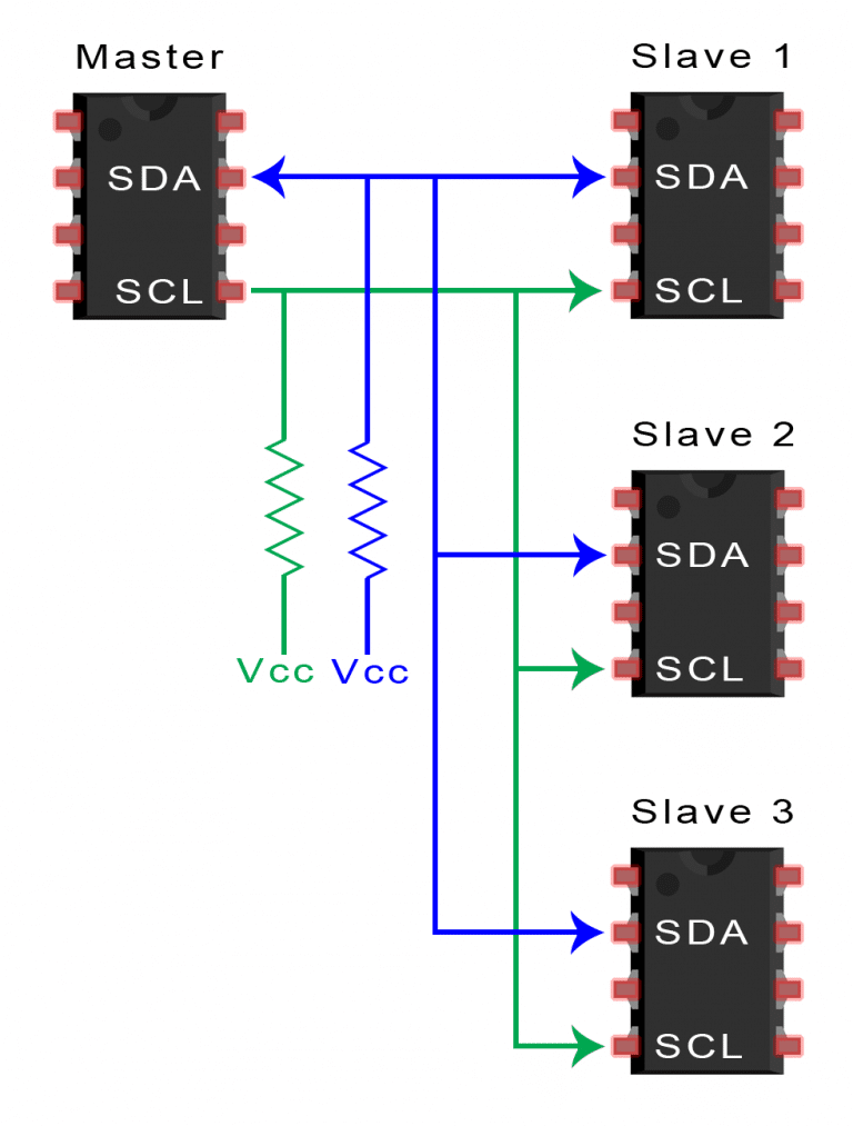 Multiple Masters vs Multiple Slaves I2C supports multiple masters connected to multiple slaves simultaneously, but problems can arise when two masters attempt to send or receive data simultaneously over the SDA line.Therefore, each master must check the SDA line to see if it is low or high before sending a message.If the SDA line is low, it means another master is controlling the bus. If the SDA line is high, data can be safely sent.If you want to connect multiple masters to multiple slaves, use a 4.7K ohm pull-up resistor to connect the SDA and SCL lines to Vcc: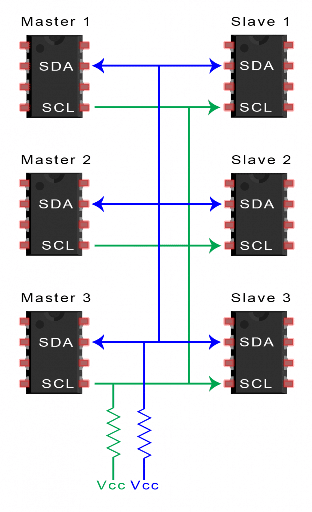
Compared to other protocols, I2C may sound complex. Below are some pros and cons to help you determine if they meet your project needs:
Advantages of I2C
-
Only uses two wires
-
Supports multiple masters and multiple slaves
-
Hardware is simpler than UART
-
Well-known and widely used protocol
Disadvantages of I2C
-
Data transmission rate is slower than SPI
-
Data frame size is limited to 8 bits
end
One-Stop Linux
Follow and reply with 【1024】 to receive a wealth of Linux materials
Collection of Wonderful Articles
Recommended Articles
☞【Collection】ARM☞【Collection】Fan Q&A☞【Collection】All Originals☞【Collection】LinuxGetting Started☞【Collection】Computer Networks☞【Collection】Linux Drivers☞【Essentials】Embedded Driver Engineer Learning Path☞【EssentialsAll Knowledge Points of Linux Embedded – Mind Map