1. Causes and Types of Errors
1. Analysis of Causes of Errors: This section elaborates on the main causes of transmission errors, including but not limited to physical medium factors (such as noise, signal attenuation), environmental interference (such as electromagnetic interference, weather effects), and equipment failures, providing examples of how these factors can lead to inconsistencies in data transmission.
2. Research on Error Control Methods: A systematic review of existing error control methods, including error detection techniques (such as parity check, CRC cyclic redundancy check) and error correction techniques (such as Forward Error Correction (FEC), Automatic Repeat reQuest (ARQ)), analyzing the working principles, advantages, disadvantages, and applicable scenarios of each method.
3. Evaluation of Method Effectiveness: For different application scenarios (such as real-time communication, file transfer, satellite communication, etc.), evaluate the effectiveness and performance of various error control methods, including key indicators such as bit error rate, transmission efficiency, and latency.
1) Causes of Errors
Illustration of the process of error generation is shown in Figure 6-13. In Figure 6-13(a), data is transmitted through the communication channel, while Figure 6-13(b) shows the impact of noise during data transmission.
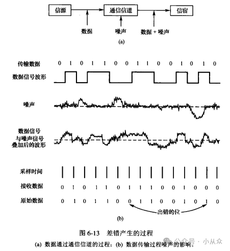
When data originates from the source and passes through the communication channel, there is always some noise present in the channel. Therefore, by the time it reaches the destination, the received signal is a combination of the signal and noise. At the receiving end, the receiving circuit samples the signal level. If the result of the noise superimposed on the signal leads to an error during level judgment, it will cause errors in the transmitted data.
2) Types of Errors
Noise in communication channels can be classified into two categories: thermal noise and impulse noise.
(1) Thermal Noise: Thermal noise is generated by the thermal motion of electrons in the conductive medium. Characteristics of thermal noise include: it is always present, has a small amplitude, and its intensity is independent of frequency; however, it has a wide spectrum and is a type of random noise. Errors caused by thermal noise are classified as random errors.
(2) Impulse Noise: Impulse noise is caused by external electromagnetic interference. Compared to thermal noise, impulse noise has a larger amplitude and is a major cause of transmission errors. The duration of impulse noise may be longer compared to the transmission time of each bit of data, thus causing multiple adjacent data bits to be erroneous in a burst manner. Transmission errors caused by impulse noise are classified as burst errors.
Transmission errors occurring during communication are composed of both random errors and burst errors.
2. Definition of Bit Error Rate
The bit error rate refers to the probability that binary code elements are transmitted incorrectly in a data transmission system, and it is numerically approximated as
P. = N./N (6-10)
Where N is the total number of transmitted binary code elements;
N is the number of code elements that were transmitted incorrectly.
a. When understanding the definition of bit error rate, the following issues should be noted:
(1) The bit error rate should be a parameter measuring the reliability of data transmission under normal operating conditions of the system.
(2) For an actual data transmission system, it cannot be generalized that a lower bit error rate is always better; the requirements for the bit error rate should be based on actual transmission needs. After determining the data transmission rate, a lower bit error rate leads to more complex transmission system equipment and higher costs.
(3) For actual data transmission systems, if the transmitted elements are not binary, they should be converted to binary elements for calculation.
b. Provided telephone line bit error rate data:
1. Data Accuracy Verification: First, please verify whether the provided telephone line bit error rate data is accurate, especially the range of bit error rates at different transmission rates (10⁻⁴~10° for 300b/s~2400b/s, 10⁻²~10 for 4800b/s~9600b/s), confirming whether there are any obvious formatting or numerical errors.
2. Technical Requirement Analysis: Next, please analyze why computer communication requires an average bit error rate lower than 10⁻⁹, and what the technical considerations and application scenarios behind this standard are.
3. Solution Exploration: Then, please elaborate on the common error control techniques that can reduce the bit error rate of ordinary telephone lines to the level required for computer communication, comparing the advantages and disadvantages of these techniques and their applicable conditions.
4. Practical Application Recommendations: Finally, based on the above analysis, provide specific technical selection recommendations and implementation steps for scenarios requiring computer communication over ordinary telephone lines.
3. Working Principle of Cyclic Redundancy Check
1) Types of Error Detection Codes
Currently, commonly used error detection codes mainly include two types: parity check codes and Cyclic Redundancy Check (CRC).
Parity check codes are the most common type of error detection code, which can be divided into vertical parity (even) check, horizontal parity (even) check, and horizontal-vertical parity (even) check (i.e., matrix code). The parity check method is simple but has poor error detection capability, generally used in environments with lower communication requirements.
CRC has strong error detection capability and is easy to implement, making it one of the most widely used error detection coding methods today.
2) Working Principle of CRC
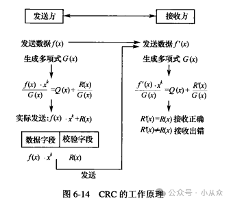
The working principle of CRC is illustrated in Figure 6-14. The CRC method works by treating the data bit sequence to be sent as the coefficients of a polynomial f(x), and at the sending end, using a pre-agreed generating polynomial G(x) to divide it, obtaining a remainder polynomial, which is then appended to the data polynomial and sent to the receiving end. At the receiving end, the same generating polynomial G(x) is used to divide the received data polynomial f(x), resulting in a calculated remainder polynomial. If the calculated remainder polynomial matches the received remainder polynomial, it indicates that the transmission is error-free; if they do not match, it indicates that there is an error in transmission, and the sender will retransmit the data until it is correct.
In practical network applications, the generation and verification process of CRC can be implemented using software or hardware methods. Currently, many communication large-scale integrated circuit chips can conveniently and quickly implement standard CRC generation and verification functions.
CRC check codes have strong error detection capabilities, capable of detecting not only discrete errors but also burst errors. Its error detection capabilities include:
(1) CRC check codes can detect all single errors;
(2) CRC check codes can detect all discrete 2-bit errors;
(3) CRC check codes can detect all odd-numbered errors;
(4) CRC check codes can detect all burst errors of length less than or equal to k bits;
(5) CRC check codes can detect burst errors of length (k + 1) bits with a probability of [1 – (1/2)k].
4. Error Control Mechanisms
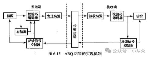
The receiving end can check whether a frame of data has errors through the error detection code. Once a transmission error is detected, the feedback retransmission (Automatic Repeat reQuest, ARQ) method is usually employed to correct it. The ARQ mechanism in data communication systems is illustrated in Figure 6-15. There are two methods for implementing ARQ error correction: stop-and-wait and continuous operation.
1) Stop-and-Wait Method
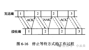
The relationship between the sending time of data frames and acknowledgment frames in the stop-and-wait method is shown in Figure 6-16.
1. Protocol Principle Analysis: A detailed explanation of the basic workflow of the stop-and-wait ARQ protocol, including data frame sending, acknowledgment frame receiving, timeout retransmission, and error handling mechanisms.
2. Efficiency Bottleneck Analysis: An analysis of the specific reasons for the low communication efficiency of this protocol, which can be quantified from the perspectives of channel utilization, waiting time, and data transmission volume.
3. Improvement Proposal Exploration: Propose at least two ideas to improve the efficiency of the stop-and-wait ARQ protocol, briefly describing their working principles and advantages.
4. Application Scenario Evaluation: Evaluate the most suitable application scenarios for the stop-and-wait ARQ protocol, explaining its advantages and limitations in those scenarios.
2) Continuous Operation Method
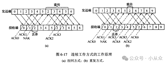
To overcome the shortcomings of the stop-and-wait ARQ protocol, the continuous ARQ protocol was proposed. There are two main methods for implementing the continuous ARQ protocol:
(1) Go-Back-N Method: The working principle of the go-back-N method is shown in Figure 6-17(a).
1. Which type of ARQ protocol does this mechanism belong to (stop-and-wait ARQ, Go-Back-N ARQ, or Selective Repeat ARQ)? Please explain the basis for your judgment.
2. Assuming that frame numbers are represented in 3-bit binary, what is the maximum size of the sending window?
3. If during the retransmission of frames 2, 3, 4, and 5, frame 3 is transmitted incorrectly again, how should the sender handle it?
4. Compared to Selective Repeat ARQ, what are the characteristics of this mechanism’s efficiency when the channel quality is poor? Please briefly explain the reasons.
(2) Selective Repeat Method: The working principle of the selective repeat method is shown in Figure 6-17(b).
When the sender has sent data frames numbered 1-5, it receives an acknowledgment frame indicating that frame number 2 was transmitted incorrectly:
1. The subsequent operation flow and data frame sending order of the sender under the selective repeat method.
2. The subsequent operation flow and data frame sending order of the sender under the go-back-N method.
3. A comparative analysis of the efficiency of the two methods in this scenario (including the number of retransmitted frames, transmission delay, etc.).
Previous Recommendations
Case Study of Analog Input for S7-200SMART PLC
Servo Positioning Address Switching
Introduction and Application of Bit Processing Instructions for FX5U PLC
How to Use Structured Variables to Create Panel Instances in WINCC7.5
How to Implement Short and Long Press Control for Buttons in S7-200SMART PLC
Detailed Tutorial on Connecting PLC to WiFi Using TIA Portal Software (Windows 10)
Detailed Explanation of Using Siemens TIA Portal Files (Creating, Opening, Archiving, and Restoring)
Analog Input in S7-300
How to Easily Communicate Between S7-1200 PLC and Weintek Touch Screen with DB Address, Including Error Solutions, Recommended for Collection
Understanding the Momentary, Self-Locking, and Interlocking of Contactors
How to Set Programmable Buttons in ABB Robot Teach Pendant
Identifying Transformer Faults by Sound
Issues with TIA Portal Software Program Versions
Learning How to Apply PLC Analog Inputs
Control of Traffic Lights
Polling Case of Two Frequency Converters Controlled by Mitsubishi PLC Using BD Board
S7-200SMART PLC Communication Between S7 PLCs
Ethernet Connection of Multiple Mitsubishi FX5U PLCs with Mitsubishi Touch Screen
Learning PLC Programming Starting from Cylinder Control Cases
Wiring of Siemens S7-1200 PLC with Servos
Analysis of Mitsubishi PLC Recipe Examples
Program and Memory Structure of Siemens 200 PLC
How to Implement Short and Long Press Control for Buttons in S7-200SMART PLC
Design of a Program for Motor Running for 2 Hours and Stopping for 2 Hours in Sequence
Practical Case of Siemens S7-1200 PLC Controlling Motor Forward and Reverse Rotation
Case Study of Constant Pressure Water Supply Using Siemens S7-1200 PLC