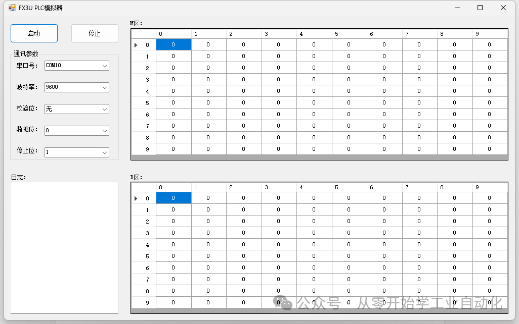
In the previous article, we implemented signal interaction simulation in the upper computer software. However, during actual debugging, it is difficult to simulate the automatic running functions of the upper computer without a PLC. Today, we will upgrade the previous Mitsubishi PLC simulator to achieve signal interaction between the upper computer and the PLC.1. Specific Interaction SignalsPrevious article:Hands-on C# Upper Computer Project Practice – Signal Interaction and Simulation between Upper Computer and PLC [Day 16 of Introduction]Signal interaction content is as follows:Signals sent from PLC to upper computer:1. Start scanning – Set M0, the upper computer determines that it has received the rising edge of M0 and starts scanning2. Start testing – Set M1, the upper computer determines that it has received the rising edge of M1 and starts testing3. Sorting and unloading completed – Set M2, the upper computer determines that it has received the rising edge of M2 and the sorting and unloading is completedSignals sent from upper computer to PLC:1. Scan OK – Set M10, PLC determines that it has received M10 and records that this battery is scanned OK2. Scan NG – Set M11, PLC determines that it has received M11 and records that this battery is scanned NG3. Test OK – Set M12, PLC determines that it has received M12 and records that this battery is tested OK4. Test NG – Set M13, PLC determines that it has received M13 and records that this battery is tested NG5. Received sorting and unloading completed, data saved – Set M14, PLC determines that it has received M14 and unloading is completed2. Implementation Logic Step 1: PLC sets M0 to start scanningWhen the upper computer starts scanning, it feeds back M10 or M11 based on the scanning results. The PLC receives M10 or M11 for the next judgment.Step 2: PLC sets M1 to start testingWhen the upper computer starts testing, it feeds back M12 or M13 based on the testing results. The PLC receives M12 or M13 for the next judgment.Step 3: PLC sets M2 to unloading completedWhen the upper computer receives the unloading completed signal and saves the data, it feeds back M14. The PLC receives M14 and returns to the first step to check if there is a signal on M0.3. Interface DesignOriginal interface:
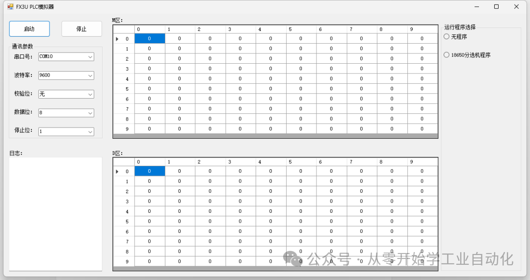
 New interface:The right side adds a program selection. If we select the 18650 program, the M values in the simulator will change according to the logic we described above.
 4. Code ImplementationThe code is too extensive, so only the PLC process logic for the 18650 sorting machine is provided.Source code can be downloaded at the end of the article
/// <summary>/// 18650 program/// </summary>private void PLCProcessLoop(){    while (_isPLCProcessRunning)    {        try        {            // Read all signal states            bool m0 = GetMValue(0);    // PLC trigger: start scanning            bool m1 = GetMValue(1);    // PLC trigger: start testing            bool m2 = GetMValue(2);    // PLC trigger: unloading completed            bool m10 = GetMValue(10);  // Upper computer feedback: scan OK            bool m11 = GetMValue(11);  // Upper computer feedback: scan NG            bool m12 = GetMValue(12);  // Upper computer feedback: test OK            bool m13 = GetMValue(13);  // Upper computer feedback: test NG            bool m14 = GetMValue(14);  // Upper computer feedback: unloading completed confirmation
            switch (_currentPLCState)            {                case PLCProcessState.Idle:                    // Step one: PLC sets M0, triggers scanning                    if (!m0)                    {                        Log("PLC: Set M0, request upper computer to start scanning");                        SetMValue(0, true);                        _currentPLCState = PLCProcessState.WaitScanFeedback;                    }                    break;                case PLCProcessState.WaitScanFeedback:                    // Wait for upper computer feedback M10 or M11                    if (m10 || m11)                    {                        if (m10) Log("PLC: Received upper computer feedback M10 scan OK");                        if (m11) Log("PLC: Received upper computer feedback M11 scan NG");                        // Reset M0                        SetMValue(0, false);                        // Reset M10\\11                        SetMValue(10, false);                        SetMValue(11, false);                        // PLC sets M1, triggers testing process                        Log("PLC: Set M1, request upper computer to start testing");                        SetMValue(1, true);                        // Change state                        _currentPLCState = PLCProcessState.WaitTestFeedback;                    }                    break;                case PLCProcessState.WaitTestFeedback:                    // Wait for upper computer feedback M12, M13                    if (m12 || m13)                    {                        if (m12)                        {                          Log("PLC: Received upper computer feedback M12 (test OK)");                         }                        if (m13)                        {                          Log("PLC: Received upper computer feedback M13 (test NG)");                        }                        // Reset M1                        SetMValue(1, false);                        // Reset M12\13                                           SetMValue(12, false);                        SetMValue(13, false);                        // Set M2, unloading                        Log("PLC: Set M2, waiting for upper computer to complete unloading");                        SetMValue(2, true);                        // Change to next state                        _currentPLCState = PLCProcessState.WaitDischargeFeedback;                    }                    break;                case PLCProcessState.WaitDischargeFeedback:                    // Wait for upper computer feedback M14                    if (m14)                    {                        Log("PLC: Received upper computer feedback M14 unloading completed signal");                        // Reset M2                        SetMValue(2, false);                        // Reset M14                         SetMValue(14, false);                        // Return to idle state                        Log("PLC: Process completed, device returns to idle state");                        _currentPLCState = PLCProcessState.Idle;                        // This time ends, next time starts after 2 seconds                         Thread.Sleep(2000);                    }                    break;            }
            // Detection interval: 200ms            Thread.Sleep(200);        }        catch (Exception ex)        {            Log($"PLC process exception: {ex.Message}");        }    }}
5. SimulationAs you can see, setting M0, we manually set M10 (equivalent to external communication setting it), it will automatically jump to M1, thus achieving the functionality we described earlier: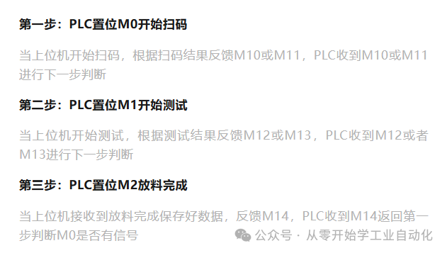 6. Conclusion Many people may ask, what is the use of this software? This is mainly used as a debugging simulator to implement the serial communication function of Mitsubishi PLC. We can write some logic ourselves, allowing us to learn without needing physical devices during upper computer software debugging.Source code can be downloaded for free:Send “3009” to the public account to download.If you like it, please followto support us, and you can also enter the communication group through the public account menu. Thank you all for your support.Essential debugging tool: Virtual Serial Port detailed installation tutorial (available for download)Hands-on C# Upper Computer Project Practice – TCP, Serial Communication Connection Implementation [Day 13 of Introduction]Mitsubishi PLC GX Works3 ST Language Programming Introduction – Lesson 1: Creating ST Programs and Simple Arithmetic Programming