1. Introduction
1.1 Project Development Background
With the deep penetration of smart home technology and the rapid development of embedded microcontroller (MCU) technology, the application of large-scale integrated circuits in the consumer electronics field is becoming increasingly widespread. Home lighting devices are upgrading from “single lighting” to “smart adaptation and humanized services.” As a core lighting device in homes, offices, and study scenarios, desk lamps are used frequently, but traditional desk lamps have many pain points:
Energy Waste: Users often forget to turn off the desk lamp, leading to prolonged idle operation and unnecessary energy consumption;
Inconvenient Operation: In dark environments at night, users need to fumble for the switch, posing a risk of bumping into things;
Poor Light Adaptability: Fixed brightness and color temperature cannot meet the needs of different scenarios (such as reading, drawing, and screen backlighting), leading to visual fatigue over time, and even affecting color judgment in drawing due to color temperature deviation;
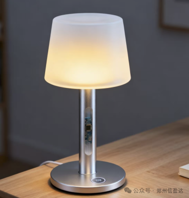
The visual night light control system based on the STM32F103RCT6 microcontroller has emerged to address these pain points by integrating four core technologies: human body sensing, light detection, PWM dimming, color temperature adjustment, and alarm control. The system supports multiple mode switching, timed alarms, and automatic sensing start-stop, adapting to scenarios such as reading, drawing, and screen backlighting, providing users with an energy-saving, comfortable, and convenient lighting experience, suitable for home studies, student dormitories, offices, etc., with high practical value and market promotion potential.
1.2 Functional Design Implementation
This system focuses on the core goals of “intelligent sensing, on-demand dimming, scene adaptation, and controllable timing,” achieving the following functions:
Timed Alarm Function: Users can set the alarm time according to their needs, and the desk lamp can automatically turn on or off when the alarm time is reached.
Human Body Sensing Automatic Start-Stop: The PIR module detects human activity within the range of the desk lamp; when human activity is detected and the ambient light is insufficient, the desk lamp automatically turns on;
Light Sensing Intelligent Adjustment: The system collects ambient light intensity in real-time through a light-sensitive resistor sensor, dynamically adjusting the desk lamp output based on light intensity: increasing brightness when light is weak and decreasing brightness when light is strong.
Intelligent Light Source Mode: Automatically reads ambient light and human activity status to adjust the brightness of the light.
Drawing Mode: Presents a cooler color temperature based on ambient light to reduce color distortion on drawing paper, making drawing more professional.
Reading Mode: Presents a medium color temperature based on ambient light to protect eyesight, preventing fatigue during long reading sessions.
Supplementary Light Mode: Presents a warmer color temperature based on ambient light to neutralize screen blue light, reducing eye strain from screen use.
1.3 Project Hardware Module Composition
(1) Main Control Chip: STM32F103RCT6
Based on the ARM Cortex-M3 architecture, with a main frequency of 72MHz, it has peripherals such as ADC, timers (TIM2/TIM3), GPIO, EEPROM, etc.; responsible for coordinating sensor data collection, RGB light control, alarm management, mode switching, and LCD display, ensuring real-time system response.
(2) Human Body Sensing Module
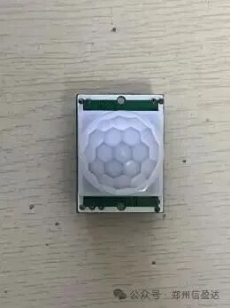
The SR602 is based on the principle of passive infrared detection, with a detection range of 5 meters and adjustable sensitivity; it outputs high and low level signals (human detected → high level, no human detected → low level), providing trigger conditions for the automatic start-stop of the desk lamp.
(3) Light Sensing Module
Light-sensitive resistor sensor, whose resistance decreases with increasing light intensity; the resistance change is converted into a 0-3.3V voltage signal through a voltage divider circuit, collected by the STM32’s ADC to determine ambient light.
(4) Lighting Module
RGB light + light beads, the RGB light is responsible for brightness and color temperature adjustment, while the auxiliary light beads are used for environmental supplementary light in intelligent light source mode, with low power consumption.
(5) Display Module
1.8-inch TFT-LCD screen, displaying in real-time: current working mode, personnel status, light conditions, etc.
1.4 Design Concept
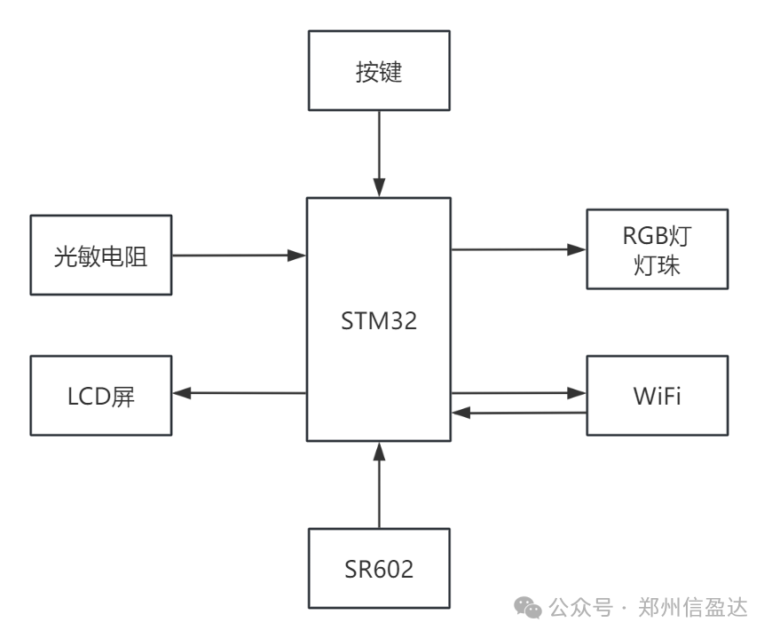
This system is built around the core of “scene-based needs, supported by multi-technology collaboration,” constructing a closed-loop control architecture of “perception – decision – execution – feedback,” with the following specific design concepts:
(1) Core Goal Decomposition
Energy Efficiency: Avoid idle operation through human body sensing + timed control;
Comfort: Multi-mode adaptation to different scenarios, with light brightness and color temperature conforming to ergonomic standards;
Convenience: Automatic sensing reduces manual operation, and the timing function aligns with rest periods;
Visualization: The LCD screen provides real-time feedback on status, and button operations are intuitive.
(2) Key Function Design
This project uses the STM32F103RCT6 as the main control unit, leveraging its rich peripheral resources to meet the demands of multi-sensor data processing and PWM dimming; the SR602 module is used for human activity detection, and the light-sensitive resistor collects light intensity, both working together to provide trigger conditions for automatic mode; the light beads, combined with PWM control, achieve a wide range of brightness adjustment, while RGB is responsible for adjusting the color temperature of the light source, and the TFT-LCD screen with independent buttons forms an intuitive human-machine interaction interface.
1.5 Development Environment Introduction
Programming Language: C language, with high execution efficiency after compilation, meeting the STM32’s requirements for real-time sensor data collection, precise PWM signal output, and alarm timing, while supporting embedded hardware driver development.
Development Tools: Keil uVision5 (MDK-ARM), with excellent compatibility with STM32F103RCT6 (Cortex-M3 core), supporting syntax highlighting, auto-completion (such as STM32 standard library functions), and generating Hex files; supports J-Link debugging, allowing real-time variable monitoring (such as light values, alarm time);Library Support: Compatible with STM32F1 standard peripheral library, simplifying initialization code for ADC, timers, GPIO, etc.;
2. Hardware Selection and Connection Diagram
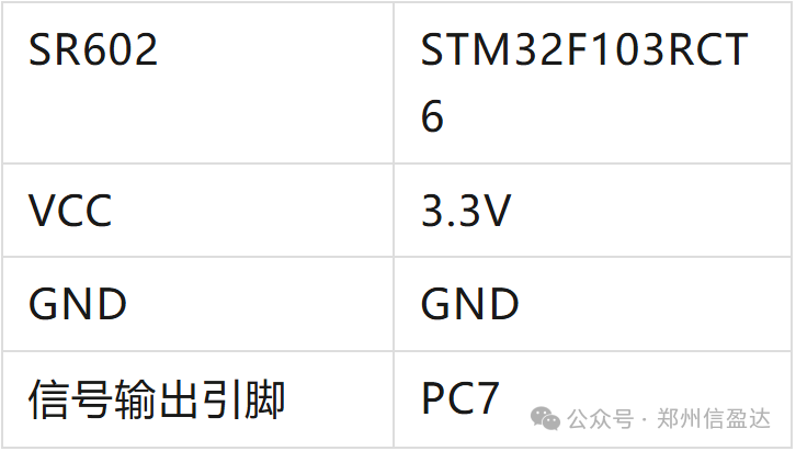
2.1 SR602 Human Body Sensing Module
Working Principle: Built-in passive infrared sensor, with a detection range of 5 meters, capable of detecting infrared radiation of about 10μm emitted by the human body; when a person moves, the infrared rays are focused on the sensor through a Fresnel lens, and the internal signal processing circuit amplifies the weak signal before outputting high and low levels.
2.2 Light-sensitive Resistor Sensor
Working Principle: Made of cadmium sulfide material, the greater the light intensity, the higher the carrier concentration, and the lower the resistance; the module converts the resistance change into a voltage signal through a voltage divider circuit. Circuit connection
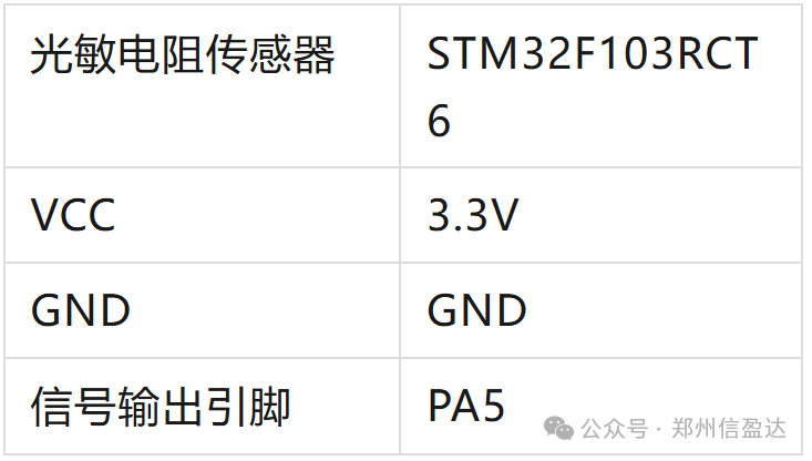
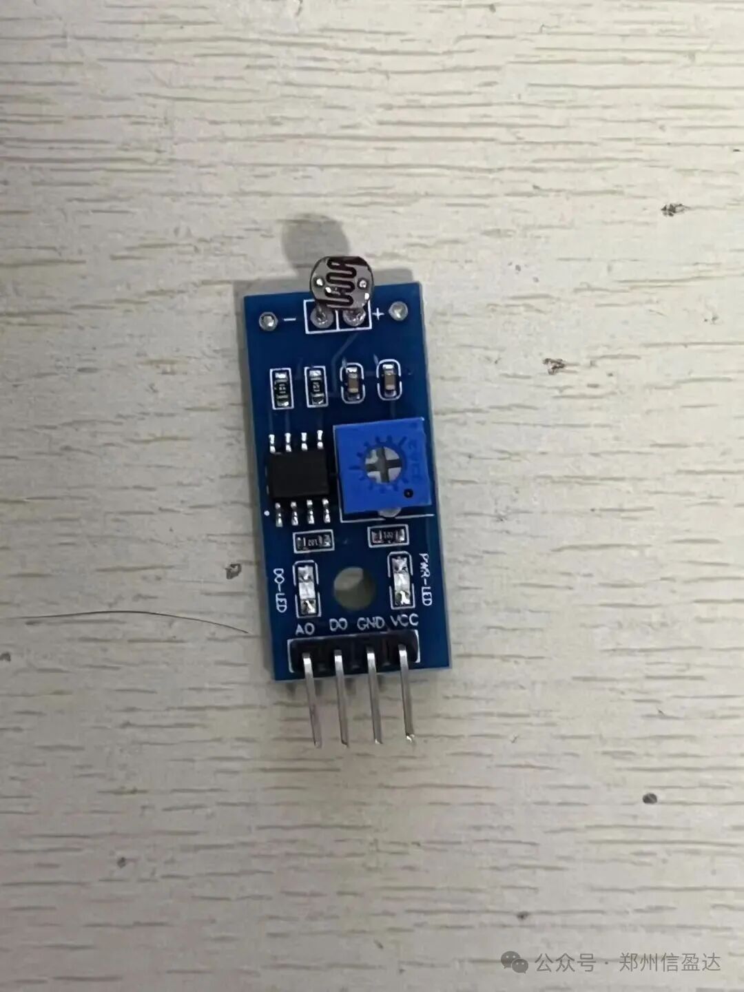
2.3 RGB Light Module
The RGB light module can emit red, green, and blue light, controlled by STM32 GPIO push-pull output, compatible with 3.3V power supply, meeting basic lighting needs.
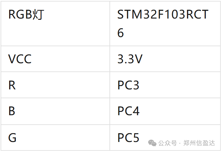
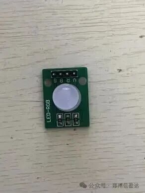
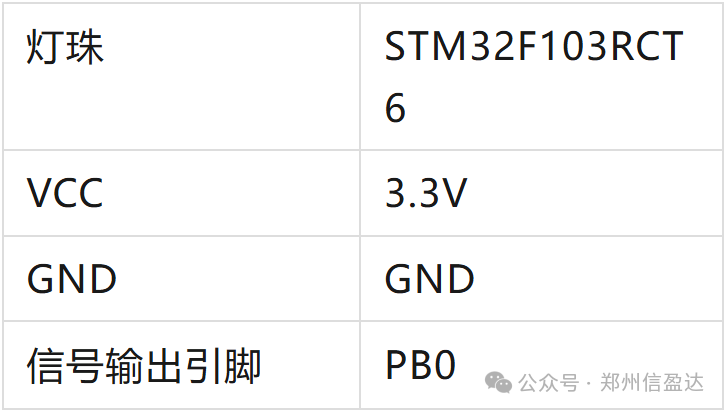
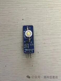
2.4 Light Beads
The light beads use PWM dimming, adjusting the brightness through the PWM signal output from the STM32’s timer. The PWM duty cycle ranges from 10% to 100%, with a larger duty cycle resulting in higher brightness.
3. STM32 Code Design
3.1 Related Module Driver Code
(1) SR602 Human Body Sensing Module Driver
#include "hr.h"
void HR_Init(void){              // Enable clock
              RCC_APB2PeriphClockCmd(RCC_APB2Periph_GPIOC,ENABLE);
              GPIO_InitTypeDef       sound_gpio = {0};                     // PC7 input--AO
              sound_gpio.GPIO_Mode = GPIO_Mode_IN_FLOATING;
              sound_gpio.GPIO_Pin  = GPIO_Pin_7;
              GPIO_Init(GPIOC,&sound_gpio);}
int Hr_Value(void){  int HRvalue = 0;       if(HR_DATA() == 1)       {
              HRvalue = 1;
       }
       else       {
              HRvalue = 0;
       }
       return HRvalue;}
(2) Light-sensitive Resistor Sensor Driver
#include "light.h"
int light = 0;
void Light_Config(void){       //1. GPIO initialization
       GPIO_InitTypeDef GPIO_InitStruct = {0};
       RCC_APB2PeriphClockCmd(RCC_APB2Periph_GPIOA,ENABLE);
       GPIO_InitStruct.GPIO_Mode = GPIO_Mode_AIN;
       GPIO_InitStruct.GPIO_Pin = GPIO_Pin_5;
       GPIO_Init(GPIOA,&GPIO_InitStruct);
       //2. Configure ADC clock --> 6 prescaler  12MHZ
       RCC_ADCCLKConfig(RCC_PCLK2_Div6);
       RCC_APB2PeriphClockCmd(RCC_APB2Periph_ADC2,ENABLE);
       //3. ADC configuration
       ADC_InitTypeDef ADC_InitStructure = {0};
       // ADC mode  independent mode
       ADC_InitStructure.ADC_Mode = ADC_Mode_Independent;
       // Scan mode  ENABLE    Single mode  DISABLE  ADC_InitStructure.ADC_ScanConvMode = DISABLE;
       // Continuous mode  ENABLE   Single mode  DISABLE  ADC_InitStructure.ADC_ContinuousConvMode = DISABLE;
       // Software trigger  ADC_InitStructure.ADC_ExternalTrigConv = ADC_ExternalTrigConv_None;
       // Right alignment  ADC_InitStructure.ADC_DataAlign = ADC_DataAlign_Right;
       // Number of channels   1  ADC_InitStructure.ADC_NbrOfChannel = 1;
       // ADC initialization  ADC_Init(ADC2, &ADC_InitStructure);
       // Regular channel configuration
       // Channel 11  Regular sequence 1  55.5 sampling cycles  ADC_RegularChannelConfig(ADC2, ADC_Channel_5, 1, ADC_SampleTime_55Cycles5);
       //ADC_RegularChannelConfig(ADC2, ADC_Channel_5, 1, ADC_SampleTime_28Cycles5);
       // Enable ADC  ADC_Cmd(ADC2, ENABLE);
       // Initialize calibration register   ADC_ResetCalibration(ADC2);
       // Wait for calibration register initialization to complete  while(ADC_GetResetCalibrationStatus(ADC2));   // Start calibration  ADC_StartCalibration(ADC2);
       // Wait for calibration to complete  while(ADC_GetCalibrationStatus(ADC2));}
int Get_Adc(void)   {
                                       ADC_SoftwareStartConvCmd(ADC2, ENABLE); // Enable specified ADC1 software conversion start function
              while(!ADC_GetFlagStatus(ADC2, ADC_FLAG_EOC )); // Wait for conversion to complete
       return ADC_GetConversionValue(ADC2);// Return the result of the last ADC1 regular group conversion}
float Get_Adc_Average(int count){
       int sum_val=0;
       int lu = 0;
       char t;
       float lightv = 0;
       float value = 0;
       for(t=0;t <count;t++)                                 </count;t++)// Loop to read times
       {
              sum_val+=Get_Adc();
       // Calculate total value
              Delay_ms(5);                 // Delay
       }
       lightv = (sum_val/count)*3.3/4096;
       value = (lightv * 1000)/(3.3-lightv);// Resistance value
       lu = sum_val/count;
       if(lu > 4095)       {
              lu = 4095;
       }
       return 4095-lu;        // Return average value
       //return value;}
(3) RGB Light Driver
#include "rgb.h"
#include "delay.h" // RGB initialization function, pins
       R--PC3,G--PC4,B--PC5
void RGB_Config(void){
       RCC_APB2PeriphClockCmd(RCC_APB2Periph_GPIOC,ENABLE);// Enable clock
       GPIO_InitTypeDef  gpioc_init ={0};
       // Define IO structure
       gpioc_init.GPIO_Mode        =GPIO_Mode_Out_PP;
       // Push-pull output
       gpioc_init.GPIO_Pin=GPIO_Pin_3|GPIO_Pin_4|GPIO_Pin_5;// Configure pins 0,1,2
       gpioc_init.GPIO_Speed       =GPIO_Speed_50MHz;// Speed 50MHZ
       GPIO_Init(GPIOC,&gpioc_init);
       Red(0);
       Blue(0);
       Green(0);}
(4) Light Bead Driver
void HW269_Config(void){
       GPIO_InitTypeDef GPIO_InitStructure = {0};
       RCC_APB2PeriphClockCmd(RCC_APB2Periph_GPIOB,ENABLE);
              GPIO_InitStructure.GPIO_Mode = GPIO_Mode_AF_PP;
       GPIO_InitStructure.GPIO_Speed = GPIO_Speed_50MHz;
       GPIO_InitStructure.GPIO_Pin = GPIO_Pin_0;
       GPIO_Init(GPIOB,&GPIO_InitStructure);
        TIM_TimeBaseInitTypeDef TIM_BaseInitStructure = {0};
       TIM_OCInitTypeDef TIM_OCInitStructure = {0};
              RCC_APB1PeriphClockCmd(RCC_APB1Periph_TIM3, ENABLE);
              TIM_BaseInitStructure.TIM_ClockDivision = TIM_CKD_DIV1;
              // Prescaler: determines the parameter for the digital filter sampling frequency, used when input capture function is involved
       TIM_BaseInitStructure.TIM_CounterMode = TIM_CounterMode_Up;
       // Count up
       TIM_BaseInitStructure.TIM_Period = 999;
       // Reload value
       TIM_BaseInitStructure.TIM_Prescaler = 71;
       // Internal auto increment of the prescaler
       TIM_TimeBaseInit(TIM3, &TIM_BaseInitStructure);
       TIM_ARRPreloadConfig(TIM3, ENABLE);// ARR preload enable
               // Output compare configuration
       TIM_OCInitStructure.TIM_OCMode = TIM_OCMode_PWM1;
       // PWM1
       TIM_OCInitStructure.TIM_OCPolarity = TIM_OCPolarity_High;// Active high
       TIM_OCInitStructure.TIM_OutputState = TIM_OutputState_Enable;// Output to corresponding pin
       TIM_OCInitStructure.TIM_Pulse = 0;                            // Compare value
       TIM_OC3Init(TIM3, &TIM_OCInitStructure);
       TIM_OC3PreloadConfig(TIM3, ENABLE);// CCR preload enable
        TIM_Cmd(TIM3, ENABLE);       // Enable timer
       HW269_OFF;       }
3.2 Main Function Framework Code
int main(){
       JTAG_SWD_Config();// Disable JTAG function, enable SWD function
       SysTick_Config(72000);// Timer initialization
       NVIC_SetPriorityGrouping(5);// Interrupt priority grouping
        USART1_Config(115200);// Serial port initialization
       RTC_Config();
       KEY_Config();
       GPIO_Config();// GPIO initialization function
       Beep_Config();// Buzzer initialization function
       HR_Init();
       RGB_Config();
       Light_Config();
       HW269_Config();
              LCD_Init();// LCD screen initialization function
       LCD_Fill(0,0,128,160,WHITE);
       LCD_ShowPicture(0,0,128,160,gImage_tu);
       LCD_ShowChinese(0,50,(u8 *)"Desk Lamp Brightness Adjustment System",BLACK,WHITE,16,0);
       LCD_ShowChinese(0,70,(u8 *)"Personnel Status",BLACK,WHITE,16,0);
       LCD_ShowChinese(0,90,(u8 *)"Light Condition",BLACK,WHITE,16,0);
       LCD_ShowChinese(0,110,(u8 *)"Mode",BLACK,WHITE,16,0);
       WIFI_Init();
       Delay_ms(1000);
       Connect_And_Send_Data();// Connect to cloud server
       Delay_ms(1000);
       BAFA_Subscribe(TOPIC);// Subscribe
       Delay_ms(1000);
       while(1)       {
                     if(rtc_runtime>1000)              {
                     sec_time = RTC_GetCounter();
                     now_time = *localtime(&sec_time);// localtime function converts the returned seconds into the current time;
                     sprintf((char *)buf,"%d/%02d/%02d %02d:%02d:%02d",now_time.tm_year+1900,now_time.tm_mon+1,now_time.tm_mday,now_time.tm_hour,now_time.tm_min,now_time.tm_sec);
                     LCD_ShowString(0,140,(const u8*)buf,BLACK,WHITE,12,0);
                     rtc_runtime = 0;
              }                            if(sr602_runtime > 100)              {
                     value = Hr_Value();
                     if(value == 1)                     {
                            LCD_ShowChinese(70,70,(u8 *)"Human Detected",BLACK,WHITE,16,0);
                            HW365(800);
                            LED1(1);
                     }                     else                     {
                            LCD_ShowChinese(70,70,(u8 *)"No Human",BLACK,WHITE,16,0);
                            LED1(0);
                            HW365(0);
                     }                            sr602_runtime = 0;
              }              if(led_runtime > 100)              {
                     light = Get_Adc_Average(10);
                     printf("light:%d\r\n",light);
                     if(light>1500)                     {
                            LCD_ShowChinese(70,90,(u8 *)"Light Detected",BLACK,WHITE,16,0);
                     }                     else if(light<1500)                     {
                            LCD_ShowChinese(70,90,(u8 *)"No Light",BLACK,WHITE,16,0);
                     }                     led_runtime = 0;
              }              if(key_runtime > 20)              {
                     key_value = KEY_Scan();
                     if(key_value == 1)// Short press key 1                     {
                            mode++;
                            if(mode == 4)                            {
                                   mode = 1;
                            }
                            HW365(0);
                     }                     if(key_value == 3)// Long press key 1                     {
                            alarm += 30;
                            if(alarm>300)                            {
                                   alarm = 60;
                            }
                     }                     if(key_value == 2)// Short press key 2                     {
                                   switch(count)                                   {
                                          case 0:LCD_ShowChinese(60,110,(u8 *)"Sleep Mode",BLACK,WHITE,16,0);Red(0);Green(0);Blue(0);break;
                                          case 1:LCD_ShowChinese(60,110,(u8 *)"Drawing Mode",BLACK,WHITE,16,0);Red(0);Green(0);Blue(1);break;
                                          case 2:LCD_ShowChinese(60,110,(u8 *)"Reading Mode",BLACK,WHITE,16,0);Red(0);Green(1);Blue(0);break;
                                          case 3:LCD_ShowChinese(60,110,(u8 *)"Supplementary Light Mode",BLACK,WHITE,16,0);Red(1);Green(0);Blue(0);break;
                                   }
                                   count++;
                                   count %= 4;
                     }                     if(key_value == 4)// Long press key 2                     {
                            alarm -= 30;
                            if(alarm<0)                            {
                                   alarm = 60;
                            }
                     }                     key_runtime = 0;
              }              if(mode == 1)              {
                     LCD_ShowChinese(60,110,(u8 *)"Alarm Mode",BLACK,WHITE,16,0);
                     if(sec_time > 1761622763 + alarm)// Timed to light up in 1 minute                     {
                            HW365(800);
                     }
              }              if(mode == 2)              {
                     LCD_ShowChinese(60,110,(u8 *)"Smart Mode",BLACK,WHITE,16,0);
                     if(light < 1500)                     {
                            HW365(800);
                     }                     else if(light >= 1500 && light <3000)                     {
                            HW365(500);
                     }                     else if(light >= 3000)                     {
                            HW365(0);
                     }                     else                     {
                            HW365(0);
                     }
              }              // BAFA cloud publish data              if(Bafa_runtime>2000)              {
                     printf("aaaaaaa%d\r\n",light);
                     BAFA_publish(TOPIC,light);
                     Bafa_runtime=0;
              }
       }
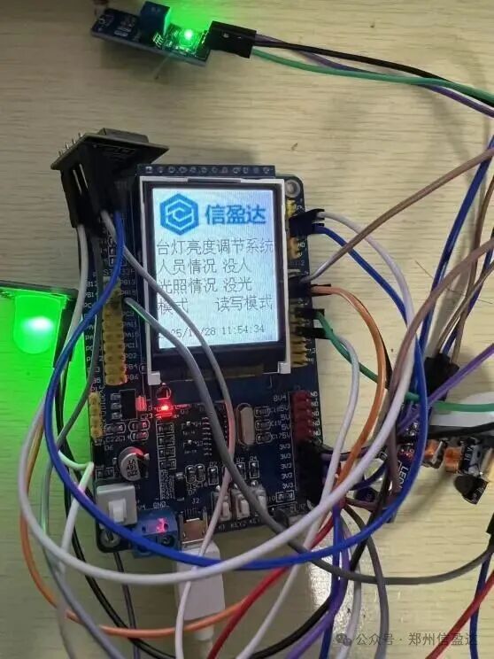
Running Result Image:
BAFA Cloud Data:
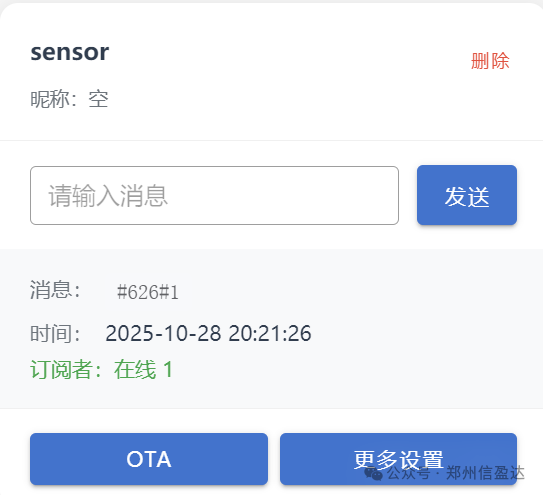
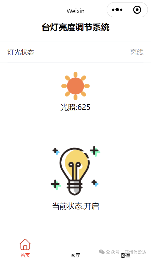
WeChat Mini Program Data:
3.3 Core Code Explanation
System Initialization: Sequentially initializes each hardware module, ensuring that peripherals (ADC, timers, GPIO) are in a ready state; after LCD initialization, it displays the system title and initial interface, enhancing user interaction experience.
Button Interaction Logic: Non-blocking reading of buttons through functions enables mode cycling, brightness adjustment, and alarm setting; mode switching automatically synchronizes the corresponding color temperature.
Sensing and Dimming Collaboration: Collects human status and light values every 100ms; when someone is present, it dynamically adjusts brightness based on the mode, and turns off the light when no one is present, balancing energy saving and convenience.
Status Display: The LCD screen updates the mode and personnel status in real-time, allowing users to intuitively grasp the system status and reduce operational blind spots.
4. Conclusion
This system, based on the STM32F103RCT6 microcontroller, successfully constructs an integrated platform for “sensing – control – timing – interaction” for automatic desk lamp brightness adjustment. The core value is reflected in three aspects, addressing pain points: avoiding fumbling in the dark to turn on the light through human sensing, reducing energy waste through timed control, and effectively solving the inconvenience and energy waste issues of traditional desk lamps by adapting to different lighting needs in various scenarios; technology integration: integrating dimming and color temperature adjustment, ADC light collection, and passive infrared human sensing technologies to achieve multi-dimensional collaborative control.
User Experience: The 1.8-inch LCD screen provides intuitive status feedback, and buttons meet the needs for mode switching and parameter setting, with an overall design that balances practicality and usability.
This system has a simple structure, high stability, and can be widely applied in homes, student dormitories, offices, etc., providing a low-cost, high-cost performance solution for the smart home lighting field.