

SPI Communication Protocol
SPI Control Mode
SPI adopts a master-slave control mode. A master device can control multiple slave devices by providing a clock and selecting the slave device. The SPI protocol also specifies that the clock for the slave device is provided by the master device through the SCK pin, and the slave device cannot generate or control the clock. Without a clock, the slave device cannot operate.
SPI Transmission Method
SPI uses synchronous data transmission. The master device generates corresponding clock pulses based on the data to be exchanged. The clock pulses form the clock signal, which is controlled by clock polarity (CPOL) and clock phase (CPHA) to determine when data is exchanged between the two SPI devices and when to sample the received data, ensuring that data is transmitted synchronously between the two devices.
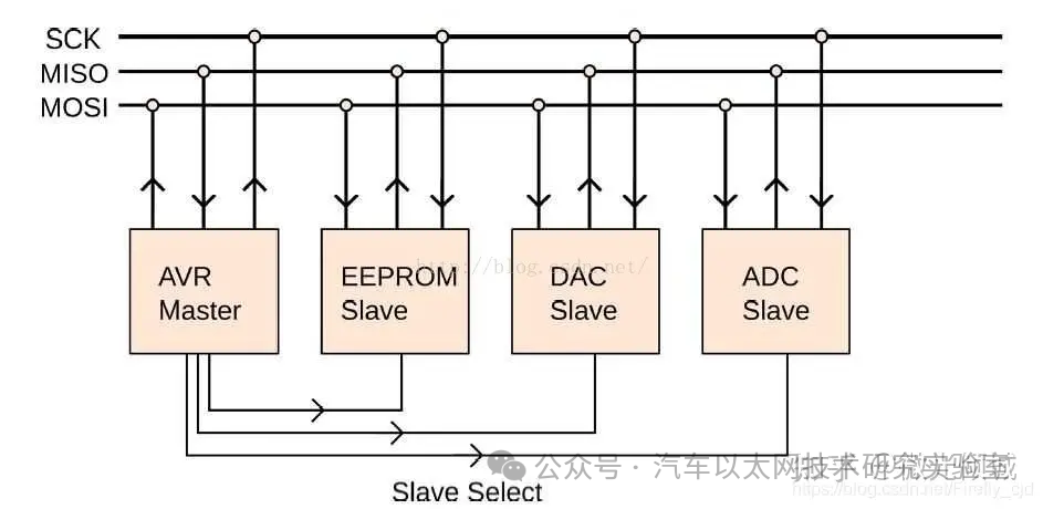
SPI Data Exchange
SPI data exchange block diagram:
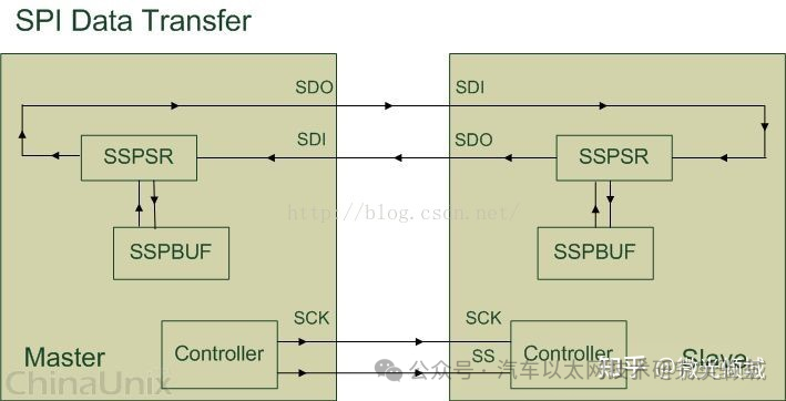
SSPBUF (Synchronous Serial Port Buffer): Refers to the internal buffer in the SPI device, typically implemented as a FIFO, which stores temporary data during transmission;
SSPSR (Synchronous Serial Port Register): Refers to the shift register in the SPI device, which shifts data in or out of the SSPBUF based on the configured bit-width;
Controller: Refers to the control register in the SPI device, which can be configured to set the transmission mode of the SPI bus.
SPI Working Mechanism
The polarity (CPOL) and phase (CPHA) of SPI are commonly referred to as CPOL and CPHA. Other notations are summarized as follows:
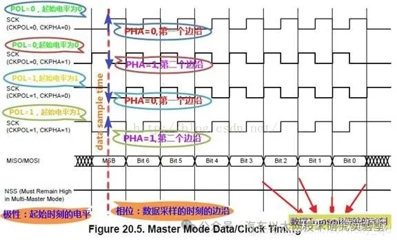
(1) CKPOL (Clock Polarity) = CPOL = POL = Polarity = (Clock) Polarity
(2) CKPHA (Clock Phase) = CPHA = PHA = Phase = (Clock) Phase
(3) SCK = SCLK = SPI Clock
(4) Edge = the moment of clock level change, either rising edge or falling edge
Within a clock cycle, there are two edges, referred to as:
Leading edge = the first edge; if the starting voltage is 1, it is when 1 changes to 0; if the starting voltage is 0, it is when 0 changes to 1;
Trailing edge = the second edge; if the starting voltage is 1, it is when 0 changes to 1 (i.e., after the first 1 changes to 0, the subsequent 0 can change to 1); if the starting voltage is 0, it is when 1 changes to 0;
CPOL Polarity
What is the idle state of the SCLK clock? It is the state of SCLK before and after sending 8 bits of data. Correspondingly, when SCLK is sending data, it is in the active state.
In English, it can be briefly explained as: Clock Polarity = IDLE state of SCK.
In detail in Chinese:
CPOL indicates whether the level of SCLK is low (0) or high (1) when idle:
CPOL=0 means the clock is idle at low level, so when SCLK is active, it is high, known as active-high;
CPOL=1 means the clock is idle at high level, so when SCLK is active, it is low, known as active-low;
CPHA Phase
Capture strobe = latch = read = sample, all refer to data sampling, the moment when data is valid. The phase corresponds to which edge (first or second) the data is sampled. 0 corresponds to the first edge, and 1 corresponds to the second edge.
For:
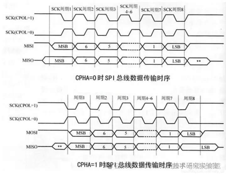
CPHA=0 indicates the first edge:
For CPOL=0, the idle state is low, the first edge is when it changes from low to high, so it is the rising edge;
For CPOL=1, the idle state is high, the first edge is when it changes from high to low, so it is the falling edge;
CPHA=1 indicates the second edge:
For CPOL=0, the idle state is low, the second edge is when it changes from high to low, so it is the falling edge;
Polarity and Phase Diagram
Software Configuration of Polarity and Phase
SPI consists of master and slave devices, which communicate via the SPI protocol.
Setting the SPI mode of the master device depends on the mode of the slave device. Therefore, it is essential to understand the SPI mode of the slave device first, and then configure the master device to match the slave device’s mode for proper communication.
For the slave device’s SPI mode, there are two types:
1. Fixed, determined by the hardware of the SPI slave device
The specific mode of the SPI slave device is described in the relevant datasheet, which must be consulted to find the relevant descriptions, such as:
Whether the SPI slave device is high or low when idle determines whether CPOL is 0 or 1;
Then find out whether the device samples data on the rising or falling edge, which allows deducing CPHA as 0 or 1 based on the determined CPOL value.
2. Configurable, set by software
The slave device is also an SPI controller that supports all four modes, and it can be set to any mode as needed.
Once the mode of the slave device is known, the SPI master device’s mode can be set to match the slave device’s mode for proper communication.
Regarding how to configure CPOL and CPHA, it is generally done by writing the corresponding bits for CPOL and CPHA in the relevant registers of the SPI controller.
Linux SPI Driver Framework
SPI Driver Architecture
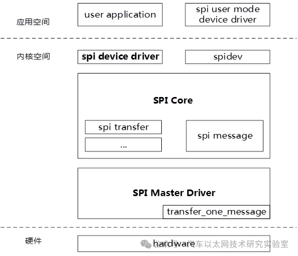
The Linux system provides excellent support for SPI devices. The SPI driver program in the Linux system can be logically divided into three parts:
1. SPI Core: The SPI Core is the core part of the Linux kernel that maintains and manages SPI. It provides operation interface functions, allowing a SPI master, SPI driver, and SPI device to register in the SPI Core during initialization and deregister during removal.
2. SPI Controller Driver: The SPI Master Driver implements hardware access operations for different types of SPI controller hardware. The SPI Master registers a controller with the SPI Core through interface functions.
3. SPI Device Driver: The SPI Driver corresponds to the driver program for the SPI device, registering with the SPI Core through interface functions. The role of the SPI Driver is to attach the SPI device to the SPI bus;
Important Structures
-
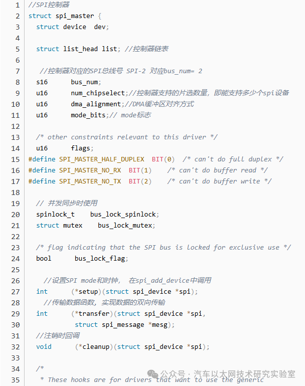
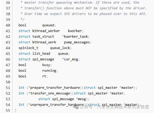
spi_master
-
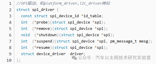
spi_driver
-
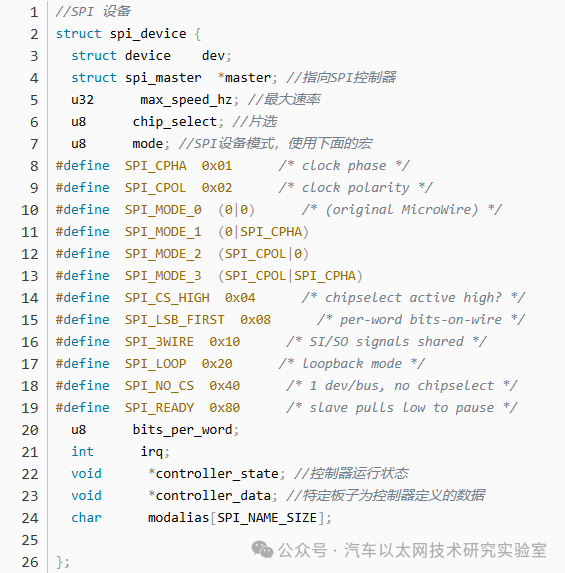
spi_device
-
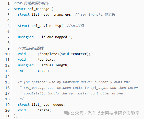
spi_message
-
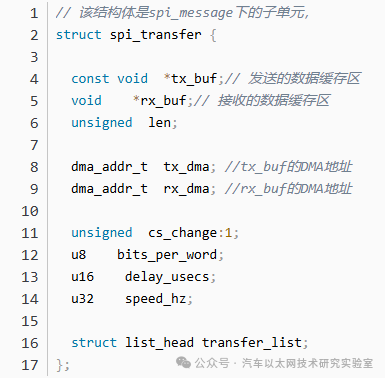
spi_transfer
The relationships between the above structures:
1. spi_driver and spi_device
spi_driver corresponds to a set of driver methods, including probe and remove methods. spi_device corresponds to the actual physical device, and each spi device requires a spi_device to describe it. The relationship between spi_driver and spi_device is one-to-many, meaning one spi_driver can support multiple spi_devices of the same type.
2. spi_master and spi_device
The relationship between spi_master and spi_device is consistent with the hardware relationship between the controller and the device, meaning spi_device is dependent on spi_master.
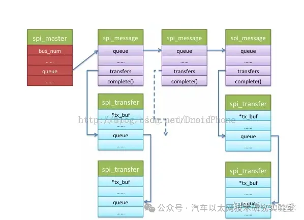
3. spi_message and spi_transfer
Data transmission in SPI is done in units of spi_message, and the content to be transmitted is in spi_transfer. spi_transfer is a subunit of spi_message.
1. The spi_transfer to be transmitted is linked as a list item in spi_transfer->transfer_list, forming a transfer_list linked list, which is attached to the spi_message’s transfers list.
2. All spi_messages waiting for transmission are linked as list items in spi_message->queue, forming a linked list attached to the queue.
API Functions
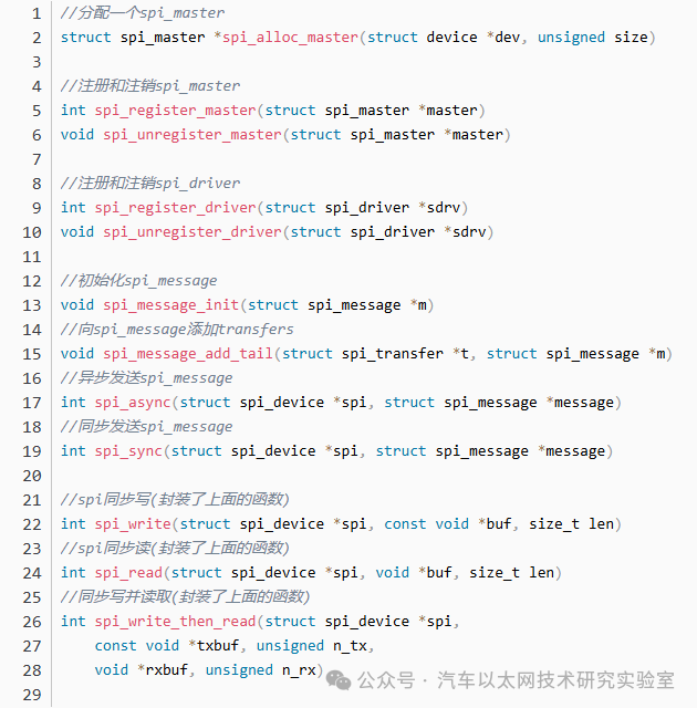
When using spi_async(), be careful not to access the buffer in the submitted spi_transfer until the complete function returns. You also cannot free the buffer that the SPI system is currently using. Once your complete function returns, those buffers are yours again.
spi_sync is synchronous; after submitting spi_message, it does not return immediately but waits until it is processed. Once it returns, the buffer can be reused. spi_sync() calls spi_async() and sleeps until complete returns.
All the above transfer functions ultimately call the transfer() function of the spi_master.
STM32 Bare Metal Driver Framework
SPI stands for Serial Peripheral Interface, which is a serial communication interface first defined by Motorola in its MC68HCXX series processors. The SPI interface is mainly used between EEPROM, FLASH, real-time clocks, AD converters, as well as digital signal processors and digital signal decoders. SPI is a high-speed, full-duplex, synchronous communication bus that occupies only four pins on the chip, saving pin space and providing convenience for PCB layout.
The SPI interface generally consists of four lines:
MISO: Master In Slave Out.
MOSI: Master Out Slave In.
SCLK: Clock signal generated by the master device.
CS: Chip Select signal controlled by the master device.
Key features of SPI include: simultaneous transmission and reception of serial data; operation as either a master or slave; programmable clock frequency; transmission end interrupt flag; write collision protection; bus contention protection, etc.
The SPI functionality of STM32 is powerful, with a maximum SPI clock of 18MHz, supporting DMA, and can be configured for either SPI or I2S protocols.
Specific hardware performance can be found in the relevant chip manual.
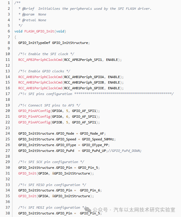
STM32 Standard Library Driver
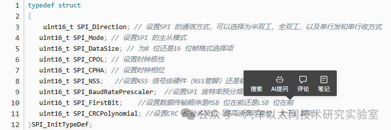
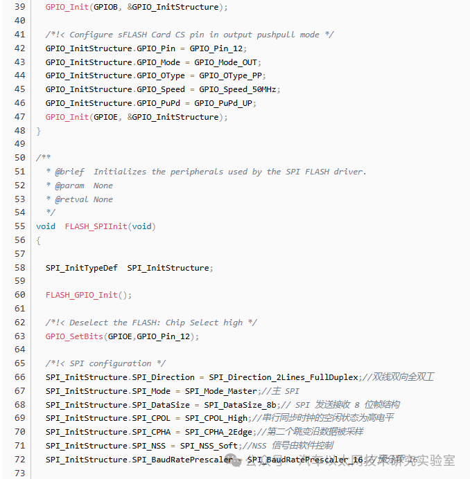
The first parameter SPI_Direction is used to set the communication mode of SPI, which can be selected as half-duplex, full-duplex, or serial transmit and receive mode. Here we choose full-duplex mode SPI_Direction_2Lines_FullDuplex.
The second parameter SPI_Mode is used to set the master-slave mode of SPI. Here we set it to master mode SPI_Mode_Master, but you can also choose slave mode SPI_Mode_Slave if needed.
The third parameter SPI_DataSize is for selecting 8-bit or 16-bit frame format. Here we are transmitting 8 bits, so we choose SPI_DataSize_8b.
The fourth parameter SPI_CPOL is used to set the clock polarity. We set the idle state of the serial synchronous clock to high level, so we choose SPI_CPOL_High.
The fifth parameter SPI_CPHA is used to set the clock phase, which determines at which edge (rising or falling) the data is sampled. It can be either the first or second edge; here we choose the second edge, so we select SPI_CPHA_2Edge.
The sixth parameter SPI_NSS sets whether the NSS signal is controlled by hardware (NSS pin) or software. Here we control the NSS signal through software rather than hardware, so we choose SPI_NSS_Soft.
The seventh parameter SPI_BaudRatePrescaler is crucial as it sets the SPI baud rate prescaler, which determines the SPI clock parameter. The prescaler can be from 2 to 256, with 8 selectable values. During initialization, we choose a prescaler value of 256, resulting in a transmission speed of 36M/256=140.625KHz.
The eighth parameter SPI_FirstBit sets the data transmission order, whether the MSB is first or LSB is first. Here we choose SPI_FirstBit_MSB, meaning the most significant bit is first.
The ninth parameter SPI_CRCPolynomial is used to set the CRC check polynomial to improve communication reliability, which should be greater than 1.
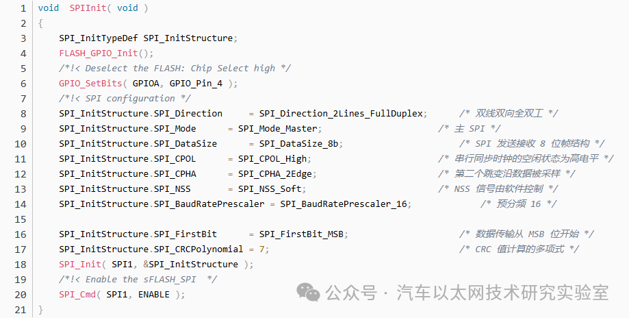
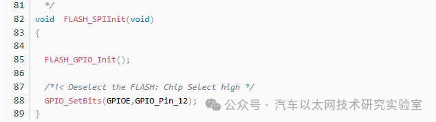
Example Code for SPI Initialization:
Applications of SPI
Common applications of SPI include NorFlash.
From the datasheet, we see that SPI transmission: CKPOL=1, CKPHA=1
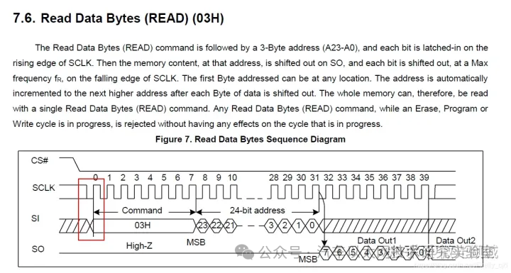
Thus, the configuration for STM32 to read NorFlash is as follows:
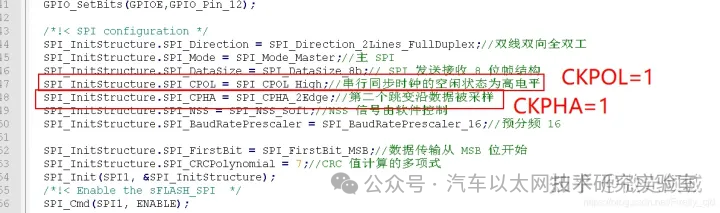
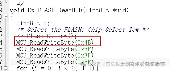
Capture the waveform of the following code:
The captured waveform is as follows:
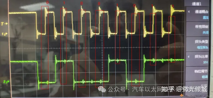
0100 1011 is 0X4B
It can be seen that:
The starting level is high, which means CKPOL=1
The second edge is sampled, which means CKPHA=1
It can also be said that the high level is effective, similar to IIC.
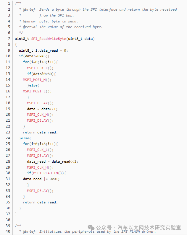
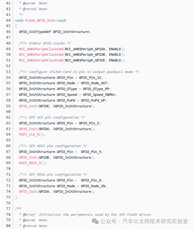
The following sentence describes the core of simulating SPI:
My understanding: data is converted on the falling edge, and sampled on the rising edge.
In addition to capturing waveforms, timing diagrams were also seen in Winbond Flash.
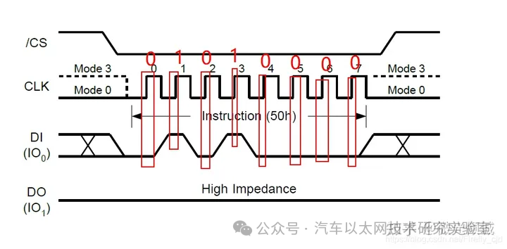
Example Code:
Reading NorFlash

Software Simulating SPI Protocol

Disclaimer: We respect originality and value sharing; the text and images are copyrighted by the original authors. The purpose of reproduction is to share more information and does not represent the position of this account. If your rights are infringed, please contact us promptly, and we will delete it immediately. Thank you!
Original link:
https://blog.csdn.net/qq_38089448/article/details/140492295