Logic Analyzer is an instrument that analyzes the logical timing of digital signals, capable of precisely capturing and displaying multiple digital signals, providing signal timing, protocol analysis, and other functions. It is also one of the most commonly used tools for embedded engineers in daily development.
Now, we can use the Haozhe RP2040 development board based on the Raspberry Pi main control chip to quickly DIY a logic analyzer at a low cost.

DIY 100M Logic Analyzer for 9.9 Yuan
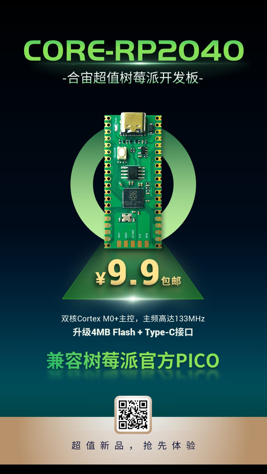
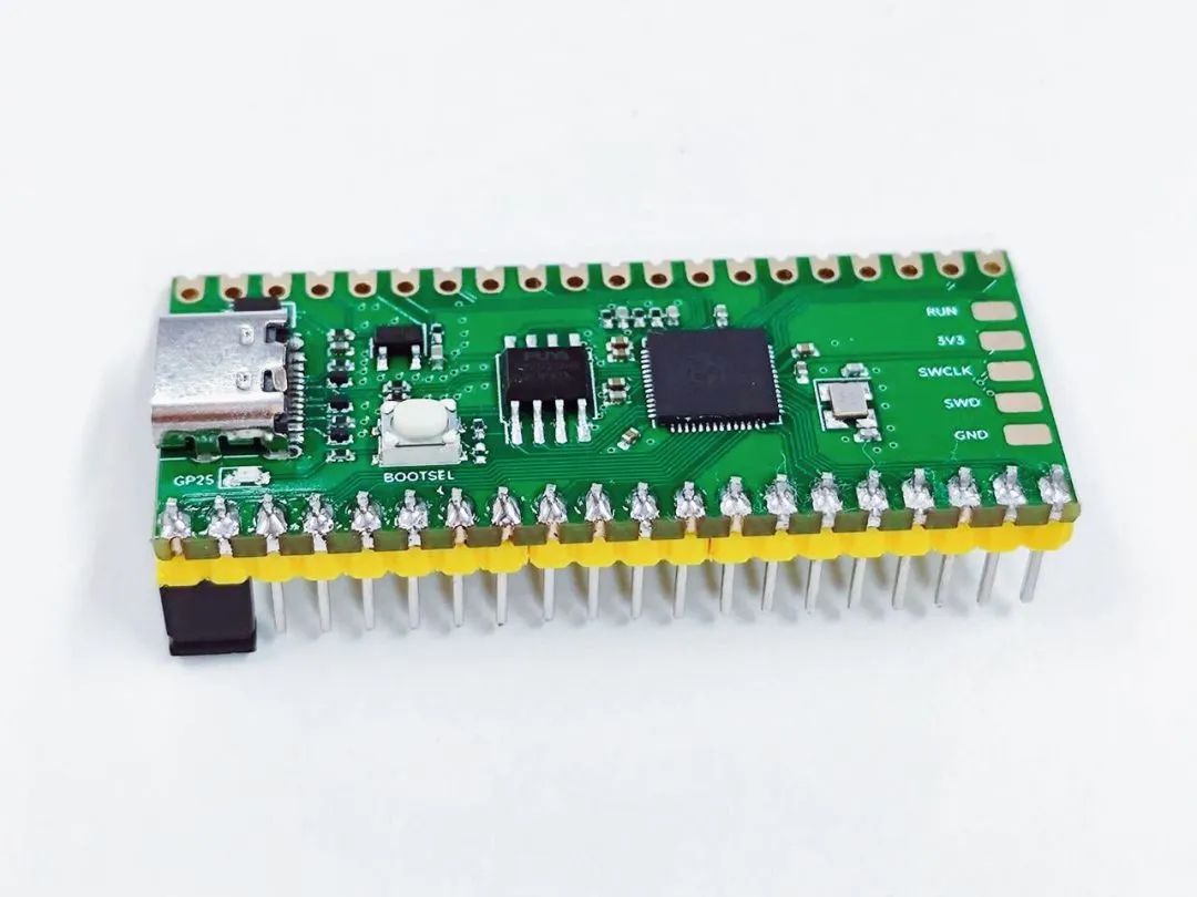
CORE-RP2040 — another new product from Haozhe’s 9.9 family, uses the Raspberry Pi RP2040 chip as the core, pin definitions compatible with the official PICO development board, and upgrades to 4MB Flash and Type-C interface based on the official version.
With open-source firmware, it can achieve the functionality of a 100M logic analyzer:
Logic Analyzer Open Source Repository:
https://github.com/gusmanb/logicanalyzer
Supported Functions
The logic analyzer based on the Haozhe RP2040 development board supports the following functions:
-
Sampling frequency from 3.1K to 100MHz;
-
Supports 24-channel input, with a maximum of 120 channels through daisy chaining;
-
Supports up to 32,767 sampling points;
-
Supports various clients, usable across all platforms.
Hardware Preparation
We need a Haozhe RP2040 development board and need to short-circuit the GP0 and GP1 pins.
Flashing Firmware
Press and hold the BOOT button, then insert USB to enter upgrade mode.
Download the firmware file, copy it to a USB drive, and it will flash successfully:
https://github.com/gusmanb/logicanalyzer/releases/download/V5.0.0.0/Firmware-LogicAnalyzer-5.0.0.0-PICO.uf2
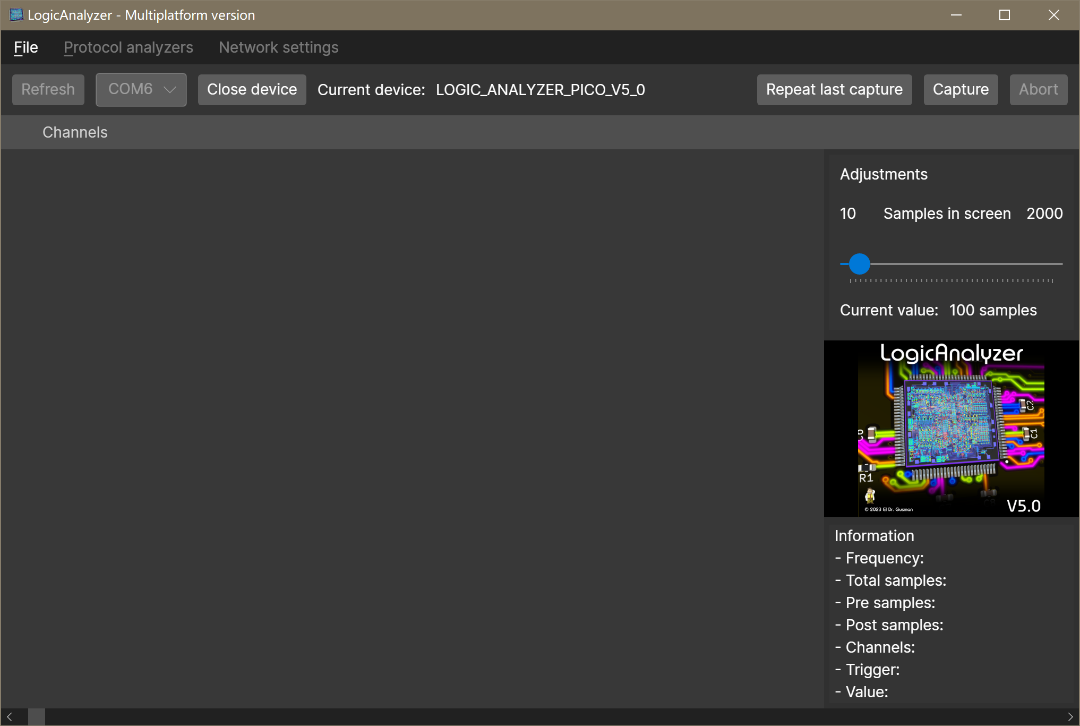
Connection Software
Here we use the client software written by the open-source repository author:
https://github.com/gusmanb/logicanalyzer/releases/latest
Download the required system version, we choose: LogicAnalyzer-5.0.0.0-win-x64.zip
Select the corresponding serial port created by the Raspberry Pi and connect:
Data Capture
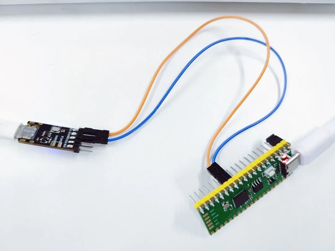
Connect the GND of the Haozhe RP2040 development board to the GND of the board we need to measure, and then connect the measurement pins to the GPIO of the development board.
The correspondence between channel numbers and GPIO numbers is as follows:
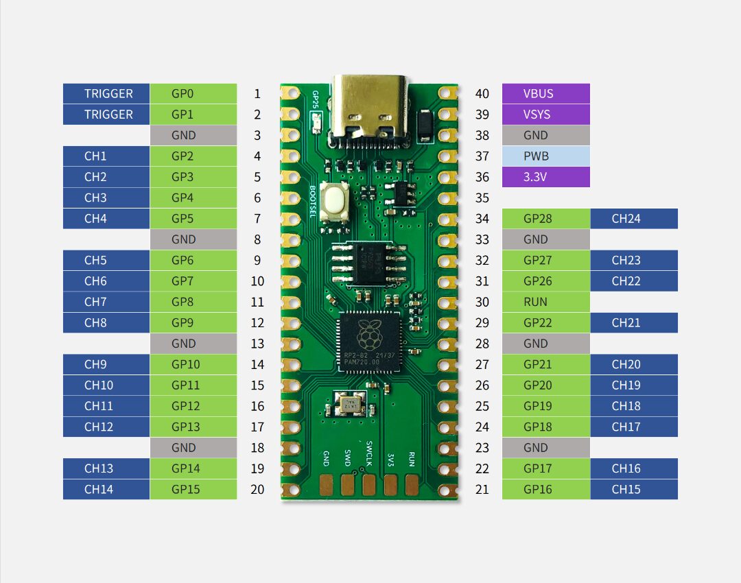
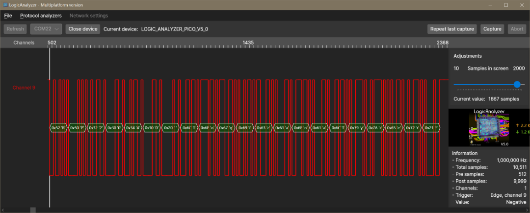
Once we connect the measured pins, we can start capturing:
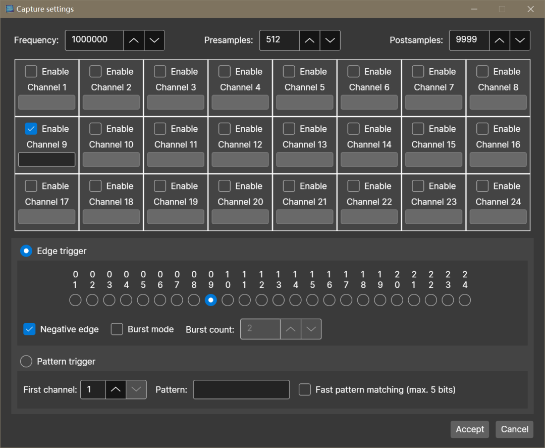
Click Capture, select the corresponding channel, capture frequency, and sample number, trigger conditions, and click Accept to start capturing:
Thank you for the attention and support from new and old friendsHaozhe grows together with you
More value-for-money new products are in preparation
Stay Tuned

 Scan QR code to join group: 645170956
– Haozhe Technical Exchange WeChat Group –
Contact Haozhe customer service to join the group with your company name

▼ Learn More About Value Products ▼
Open Source! 9.9 Shipping Development Tool — Haozhe Mini DAPLink
5 Yuan Wi-Fi/Bluetooth Dual-Mode Module
Haozhe USB3.2 Full-Function C2C Data Cable