Environment
-
Operating System: Win7, 64bit
-
IDE: CCS V3.3
-
Debugger: SEED XDS510PLUS
-
DSP Model: TMS320C6713GDP(DSP6713)
Check Steps
-
Try pressing the reset button and then click Connect.
-
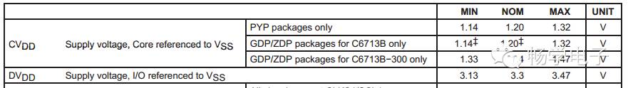
Please check if the power supply is normal (core voltage should be 1.2V, IO port voltage should be stable at 3.3V).
Use an oscilloscope to check the ripple of the power supply. The ripple range requirements are on page 99 of the TMS320C6713 datasheet.
-
If powered by a battery, check the battery voltage. Low battery voltage may cause connection failure. It is recommended to use the voltage monitoring chip TPS3823-33.
-
Check if the power-on reset is normal (there should be a reset pulse when powered on, and the reset pin should be high after powering on). The reset pin of DSP6713 has a pull-up resistor.
-
Check if the clock output is normal, including the crystal oscillator output and ECLKOUT (in TMS320C6713, default = crystal clock / 2). If the ECLKOUT pin output is abnormal, it indicates that the chip is damaged.
-
Is the GEL file loaded in the CCS3.3 project correct (e.g., “Memory Initialization”)?
-
Please ensure that the debugger is functioning properly (try swapping with a good DSP board), though it’s generally unlikely to have such issues (a debugger is quite expensive).
-
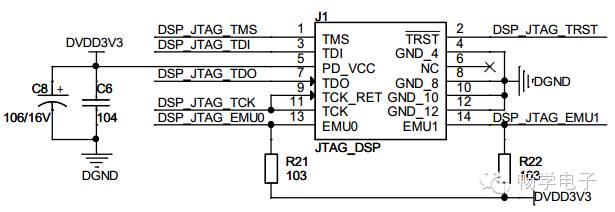
Check if there are pull-up resistors on the JTAG interface EMU0 and EMU1, and NC pins should remain unconnected.
-
Check if the PLL filter pins are correct and if the filter is soldered properly.
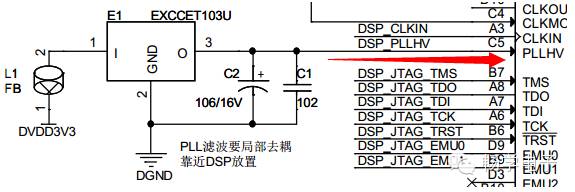
I once had a problem where the GND pin of EXCCET103 was not soldered properly, and I couldn’t connect at all.
-
Have the chip-related configurations (special pins specified in the datasheet) been configured with pull-up/pull-down resistors? TMS320C6713 requires the following configurations.
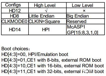
Additionally, please refer to the Datasheet to ensure the configuration of the reserved pins RSV1~7 is correct.
-
If all the above checks are correct and you still cannot connect, congratulations—you might need to replace the chip…