Keywords: Ladder Diagram, Programming Basics, Motor Start/Stop, Self-Locking, Program Download
Introduction
After getting acquainted with the hardware of the PLC, we are finally going to start “programming”! This article will guide you through a classic introductory experiment: Motor Start/Stop Control. Through this example, you will understand how PLC programs work and learn to use the most basic ladder diagram instructions.
1. Project Requirements and Analysis
Control Requirements: Press the “Start” button to run the motor; press the “Stop” button to stop the motor. Additionally, once the motor starts, releasing the “Start” button should keep the motor running (i.e., the “self-locking” function).
Hardware Connections:
-
Inputs: The start button (normally open contact) is connected to PLC I0.0, and the stop button (normally closed contact) is connected to I0.1.
-
Outputs: The contactor coil controlling the motor is connected to PLC Q0.0.
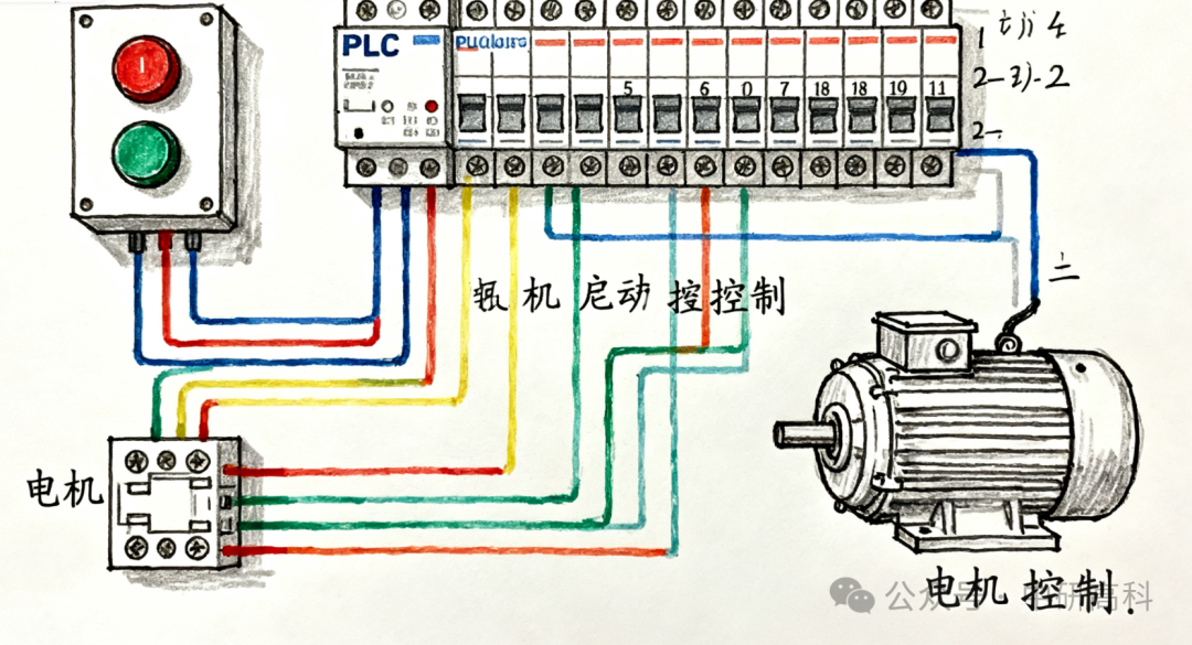
Figure 1: Schematic Diagram of Motor Start/Stop Control Hardware Connections
2. Programming Software and Instruction Introduction
We will use the S7-200 SMART as an example, utilizing the STEP 7-Micro/WIN SMART software.
Core Instructions:
-
Normally Open Contact: Represents a switch condition; when the corresponding input point has a signal, the contact is “closed”.
-
Normally Closed Contact: Opposite to normally open; it is closed when there is no signal and opens when there is a signal.
-
Coil: Represents an output; when the logical circuit it is in is closed, the coil is “energized”, and the corresponding output point has a signal.
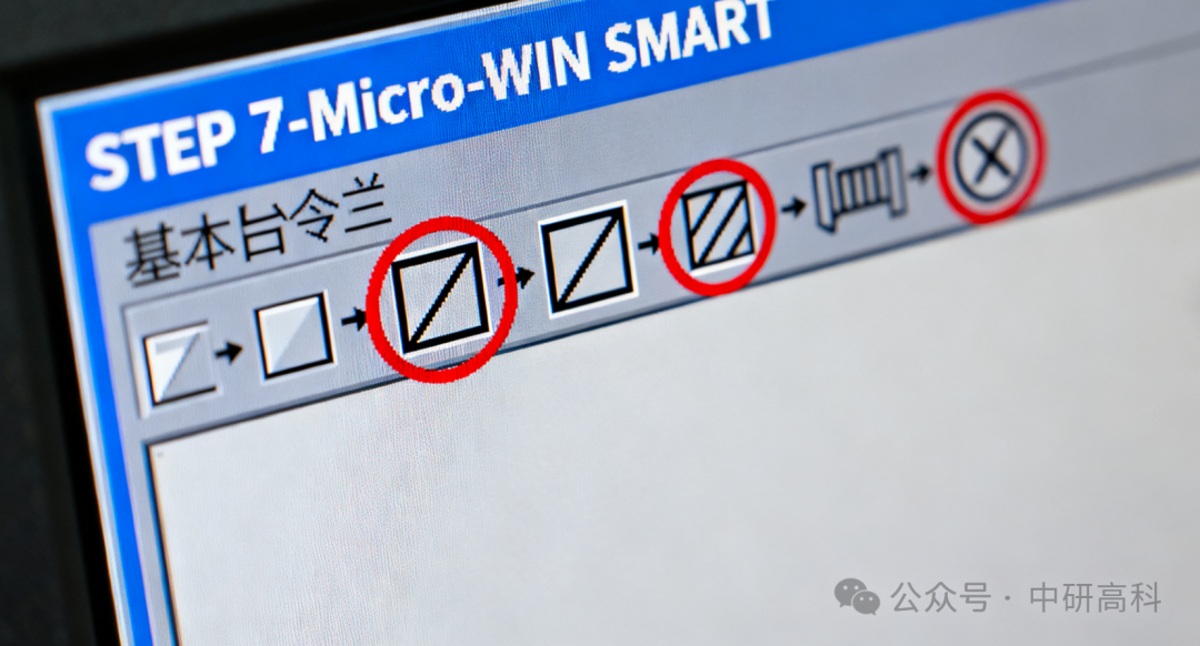
Figure 2: Screenshot of Basic Instruction Bar in STEP 7-Micro/WIN SMART Software
3. Writing the “Motor Start/Stop” Ladder Diagram Program
Ladder diagrams are a graphical programming language that resembles relay circuit diagrams, making them very intuitive.
Program Logic Breakdown:
-
Start Condition: I0.0 (Start Button) is pressed.
-
Stop Condition: I0.1 (Stop Button) must not be pressed (since it is a normally closed contact, it is normally closed and opens when pressed).
-
Self-Locking Function: When Q0.0 (Motor) is running, a normally open contact of Q0.0 is paralleled with the start button I0.0. This way, even if the start button is released, the current can still flow through the contact of Q0.0.
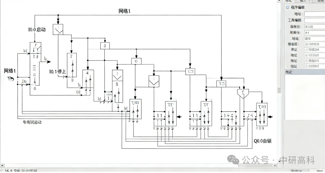
Figure 3: Complete Ladder Diagram Program for Motor Start/Stop Control
Steps:
-
Open the software and create a new project.
-
In the main program segment (usually Network 1), drag in a normally open contact, setting the address to I0.0.
-
Drag in a normally closed contact, setting the address to I0.1, in series with I0.0.
-
Drag in an output coil, setting the address to Q0.0.
-
Parallel a normally open contact below I0.0, also setting the address to Q0.0. This forms the self-locking.
4. Program Download, Debugging, and Monitoring
-
Compile: After writing the program, click the “Compile” button to check for syntax errors.
-
Connect PLC: Use a network cable to connect the computer and PLC, set the PLC’s IP address in the software, and establish communication.
-
Download: Click the “Download” button to transfer the program from the computer to the PLC.
-
Run and Monitor: Switch the PLC to RUN mode. Then click the “Program Status Monitoring” button; you will see the status of contacts and coils highlighted in green, which is very intuitive!
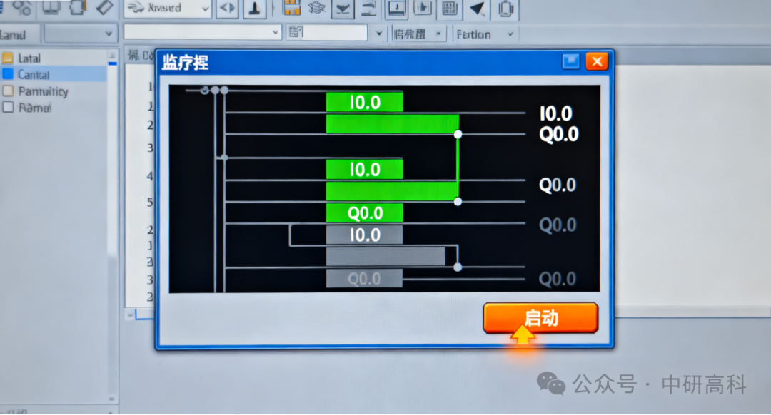
Figure 4: Program Status Monitoring View (Green Highlight Indicates Closed)

Figure 5: Physical Operation Demonstration: Press the Button and Observe the PLC Output Indicator Light Up
Conclusion
Through this simple motor start/stop project, you have successfully taken the first step into PLC practice. You have mastered the basic instructions of ladder diagrams, the concept of self-locking logic, and the methods for program download and monitoring. This logic forms the basis of most control circuits, and it is essential to understand it deeply. In the next article, we will challenge more complex applications and explore the timing and counting functions of PLCs.