A vintage Panasonic tape recorder, model RQ-517S, produced around 1975. It features a fully transistorized discrete circuit without integrated circuit chips, supporting both FM and AM dual-band reception, and mono recording and playback.
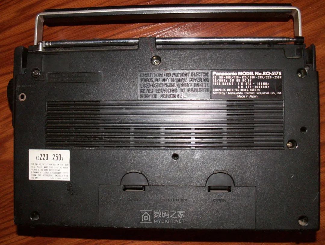
The design is a classic from that era, and this unit is portable and relatively compact. The distortion in the photo is due to the lens being too close: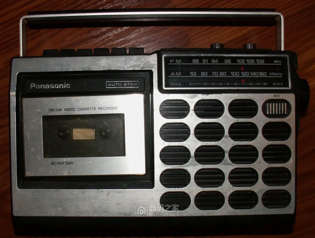 The back:
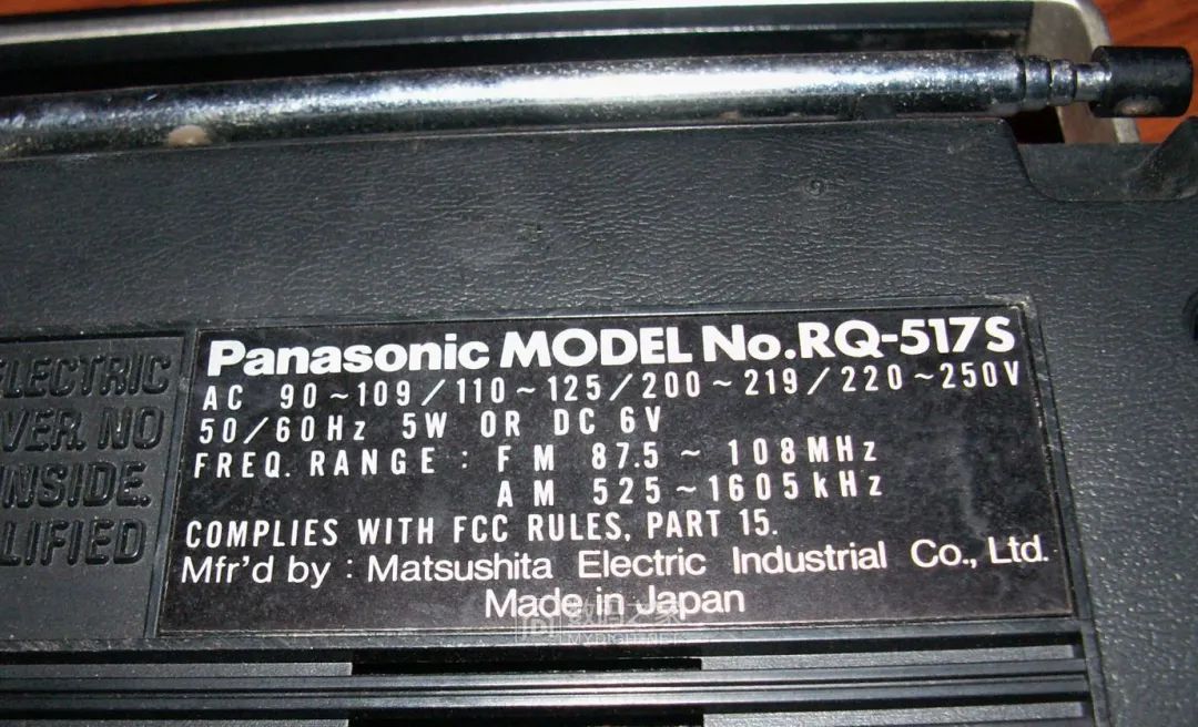
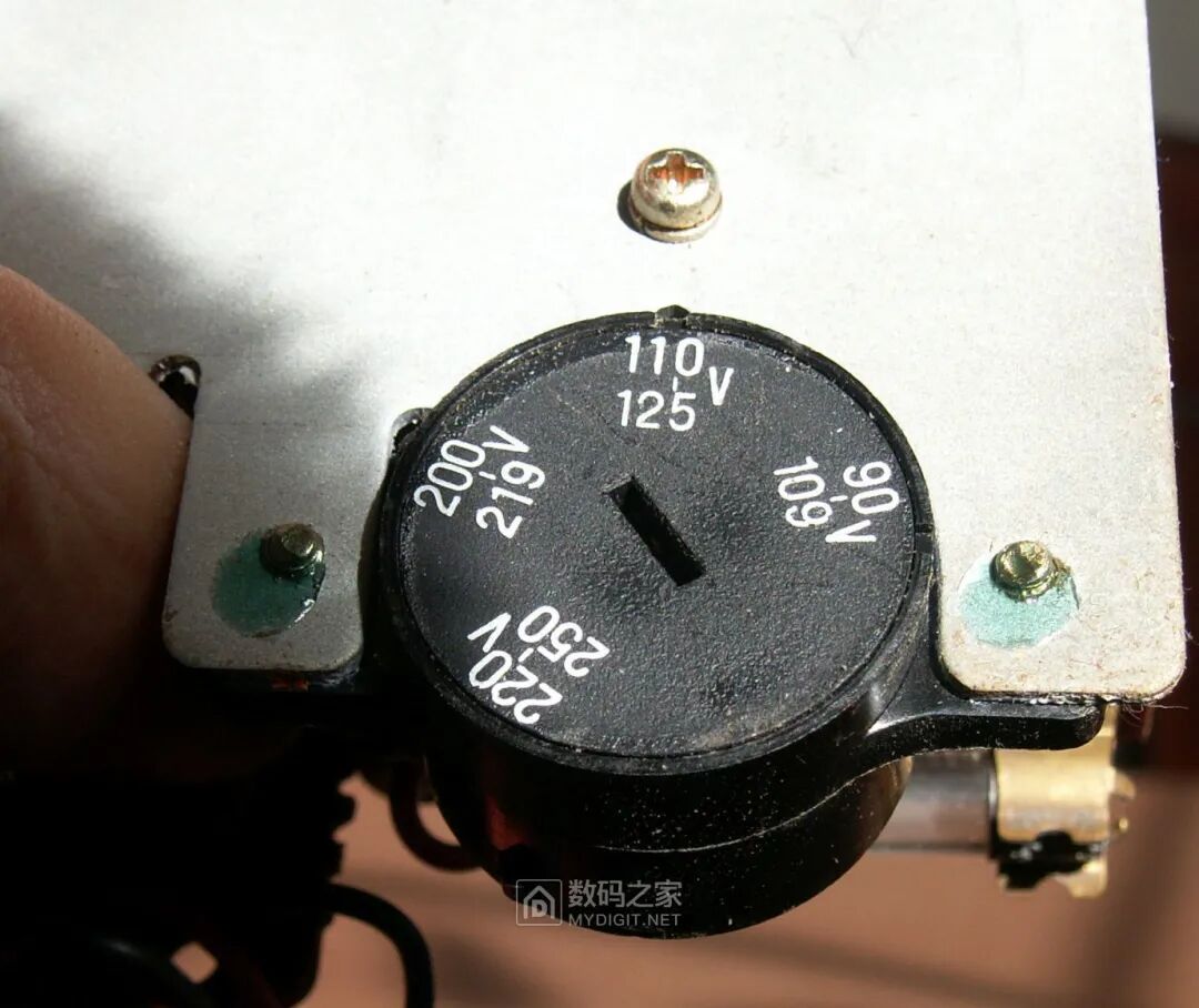
 Nameplate, produced in Japan. This tape recorder is a global model, supporting multiple country power voltages, and the frequency range for reception is also universally applicable, not limited to Japan:
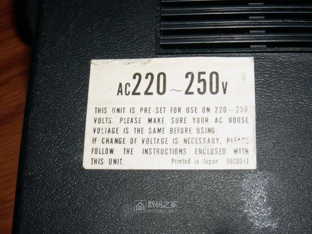
 The body has a prominent factory voltage setting warning, 220-250V:
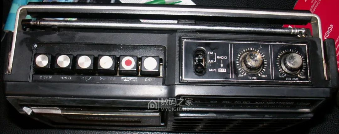
 The buttons on the top, the left six are the mechanism operation buttons, followed by the function switch to toggle between FM, AM reception, and recording/playback, with the last two knobs controlling tone and volume:
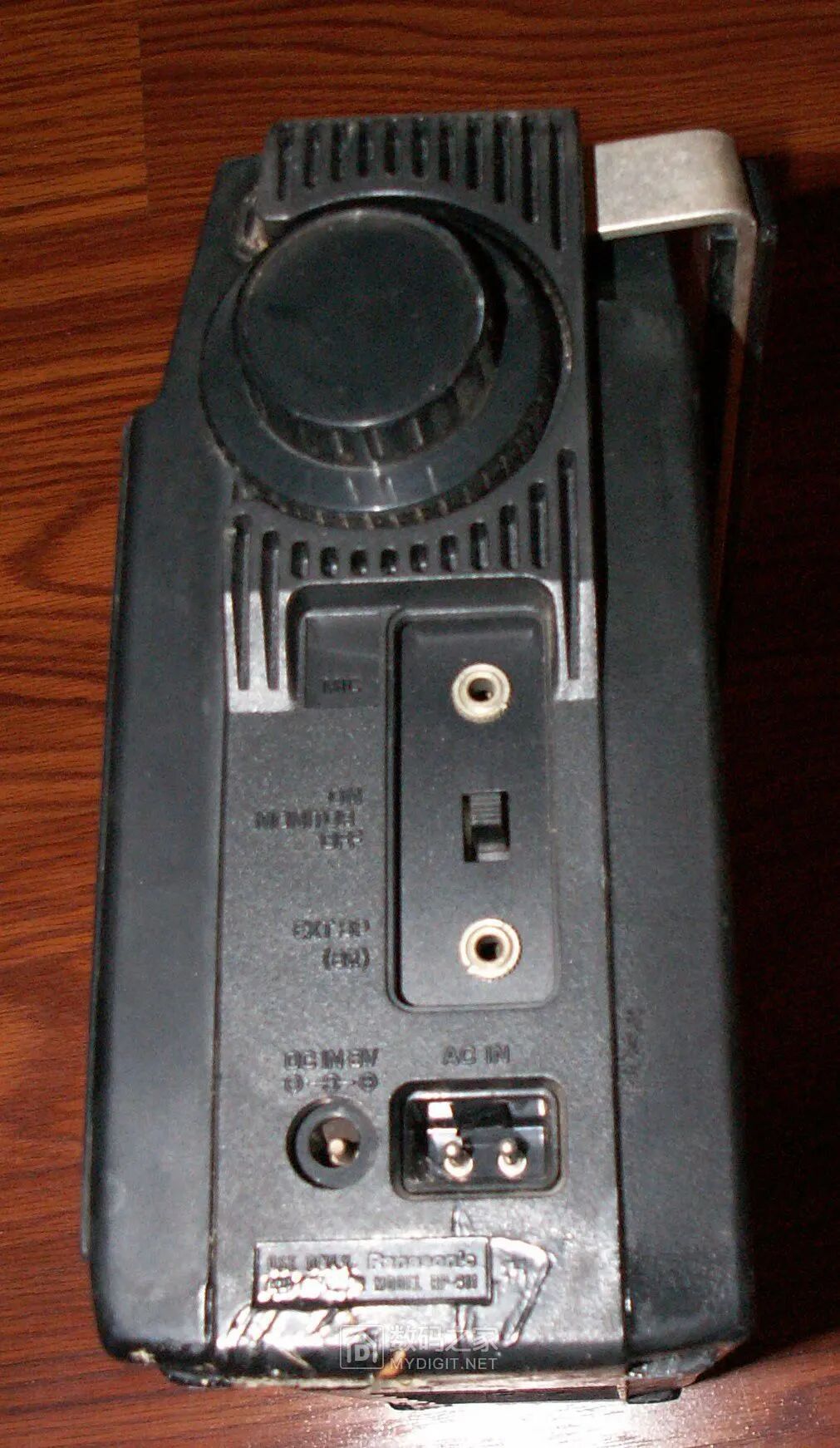
 The side features a large tuning knob for reception, an external microphone jack, a monitoring switch, and a headphone jack, with the bottom for external DC and AC power connections:
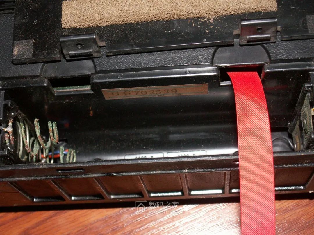
 The battery compartment holds four D-cell batteries, and the springs in the battery compartment are already rusted and need cleaning:
 Old machines like this are usually easy to disassemble because the plastic molds from that time were simple, lacking the hidden clips common today. Removing screws allows for easy removal of the front shell:
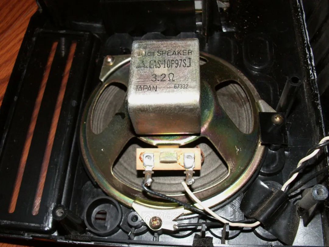
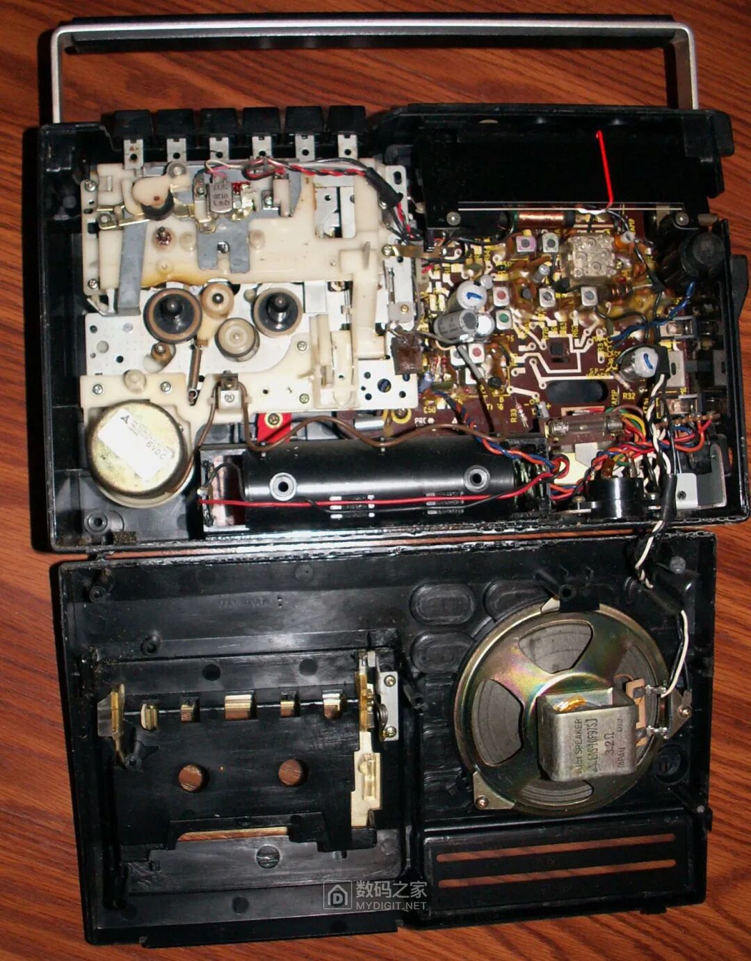 The speaker on the front shell is manufactured by Panasonic and has a magnetic shielding structure to prevent magnetic fields from affecting the tape and heads, resembling an internal magnetic speaker. This speaker has a special impedance of 3.2 ohms, and this carefully designed low-impedance speaker can achieve greater output power at lower supply voltages:
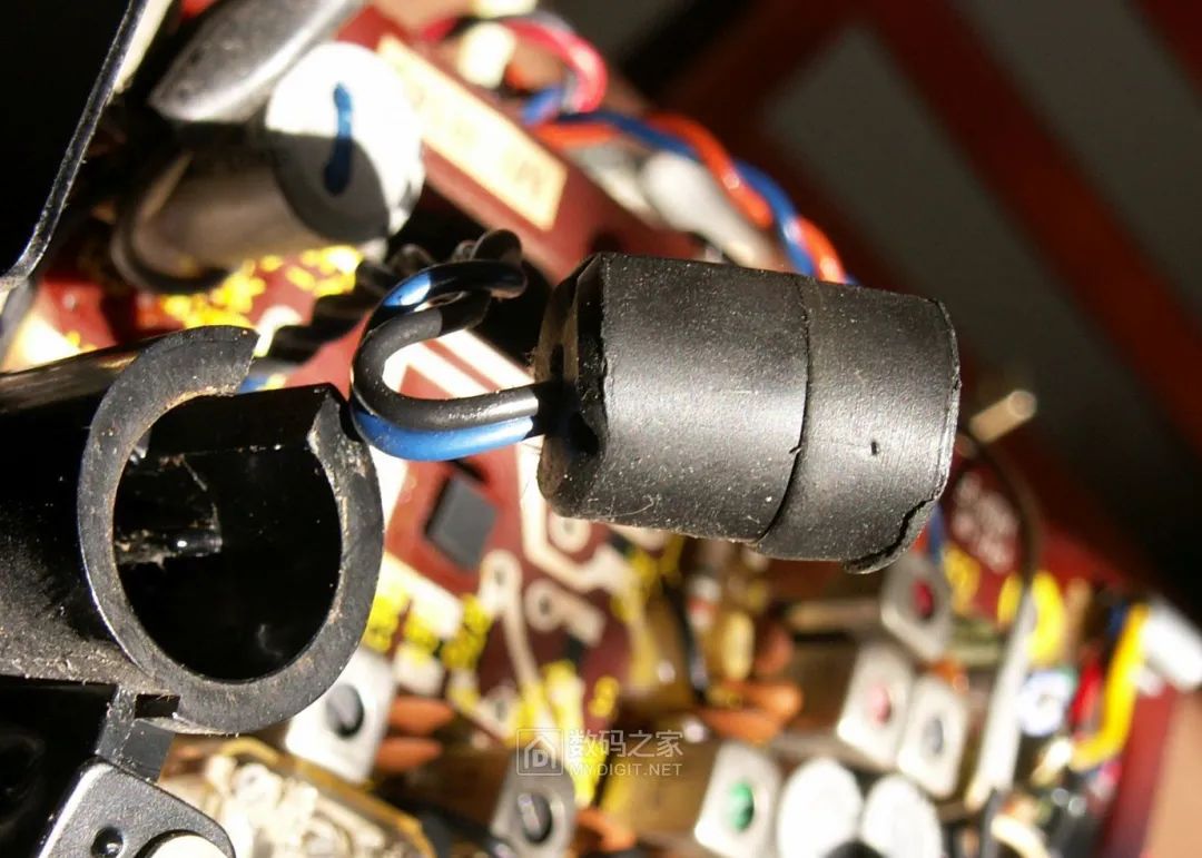
 This black object on the front shell is the internal microphone, wrapped in foam rubber to reduce noise caused by vibrations:
 The lower right corner of the interior is the AC power section: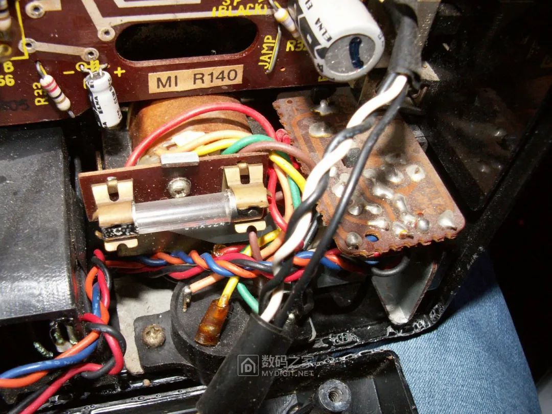
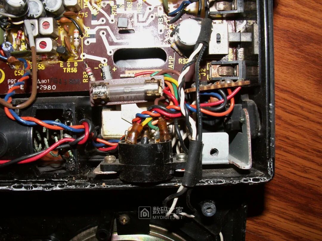 The AC power section can be removed separately, mainly consisting of a fuse, transformer, rectification and filtering circuit, and switching circuit. The transformer is quite small, estimated to be around 5W:
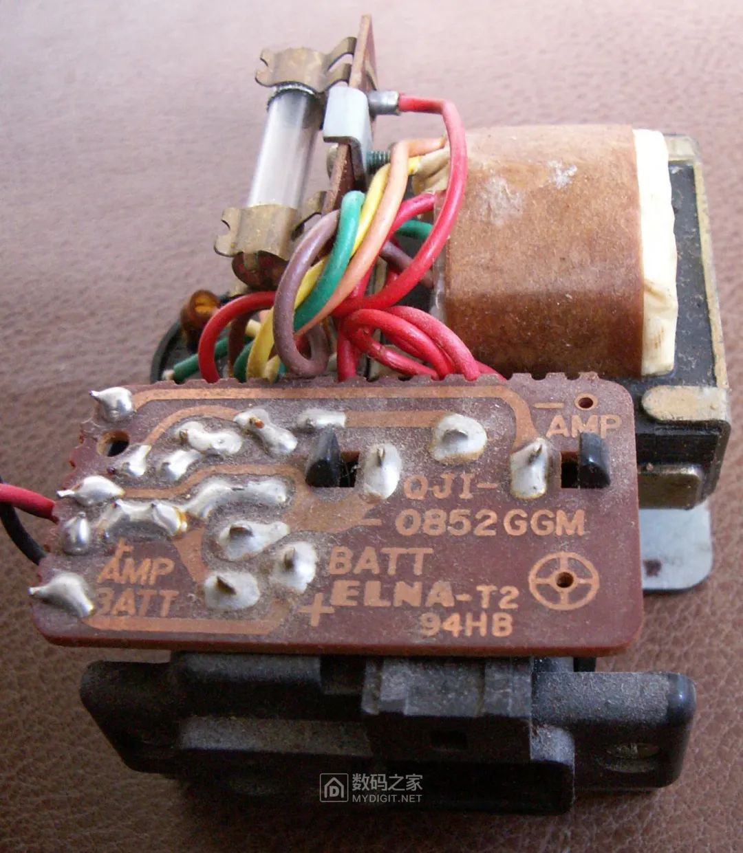 The black switch above is the voltage selection switch, allowing for selection of AC voltages from around the world: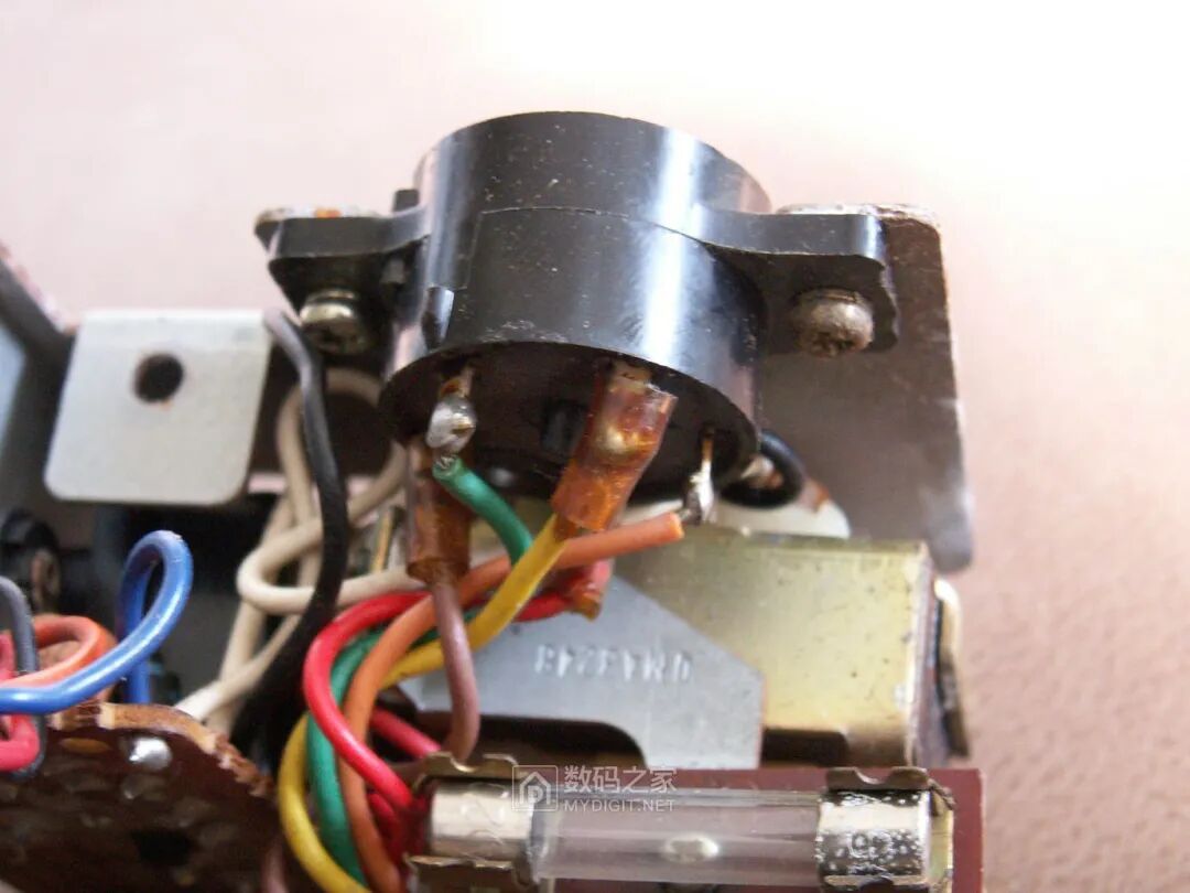
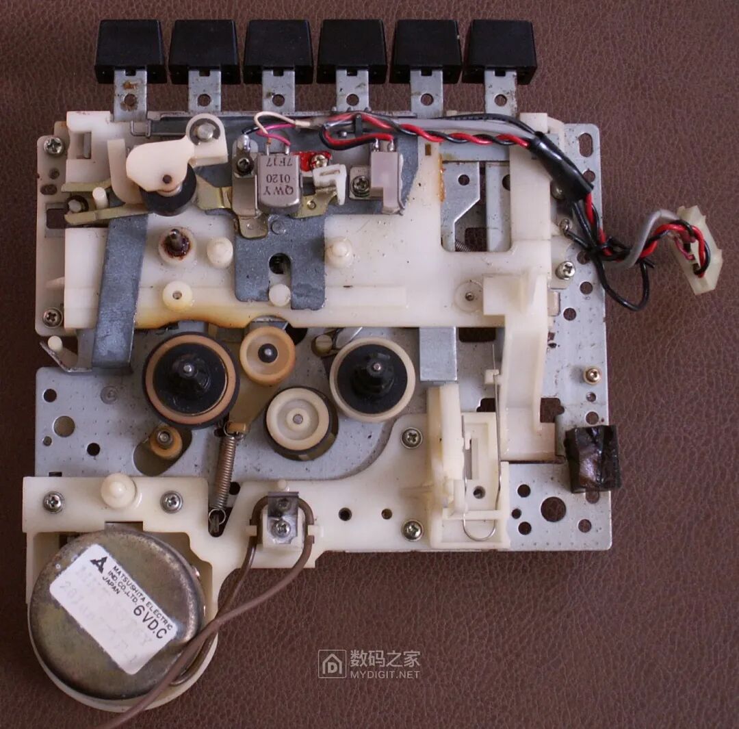
 First, repair the mechanical parts. The mechanism design from the 1970s is relatively primitive, with large size, simple shapes, and many components. The size of the magnetic head is also quite large, and this magnetic head shows no signs of wear: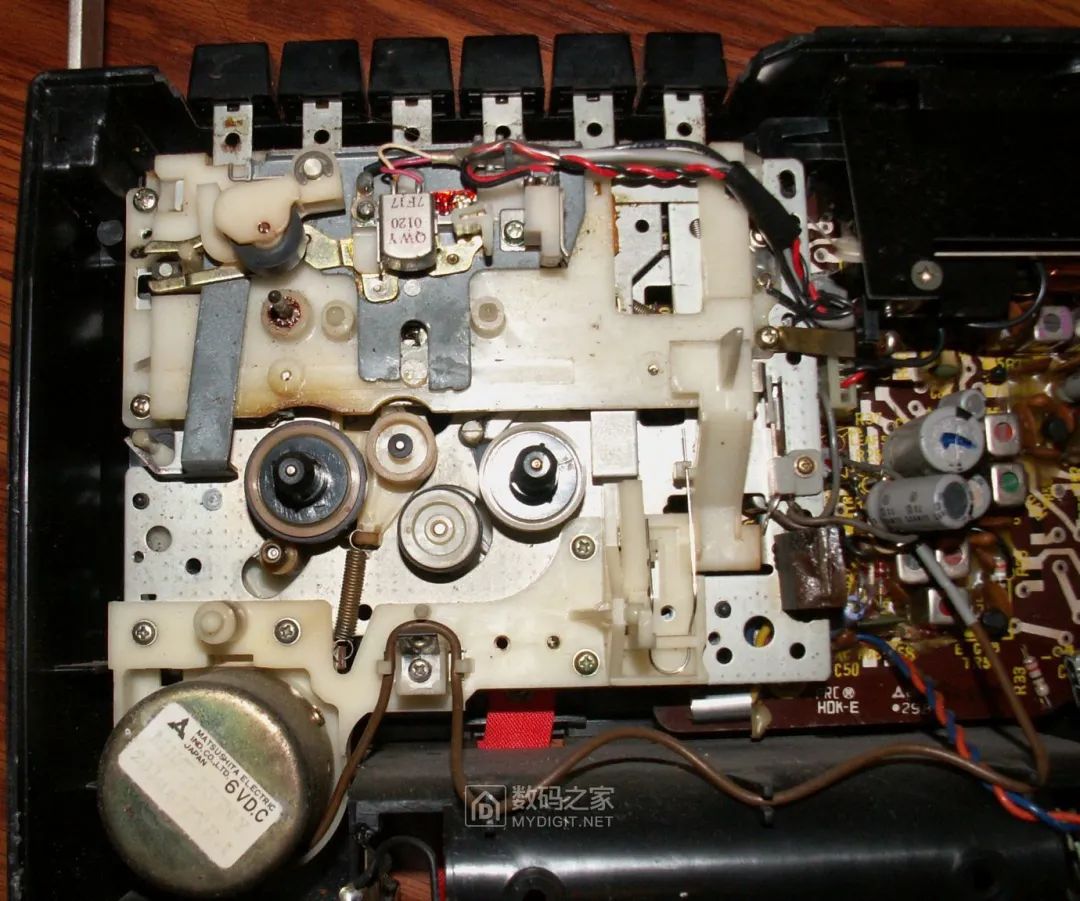
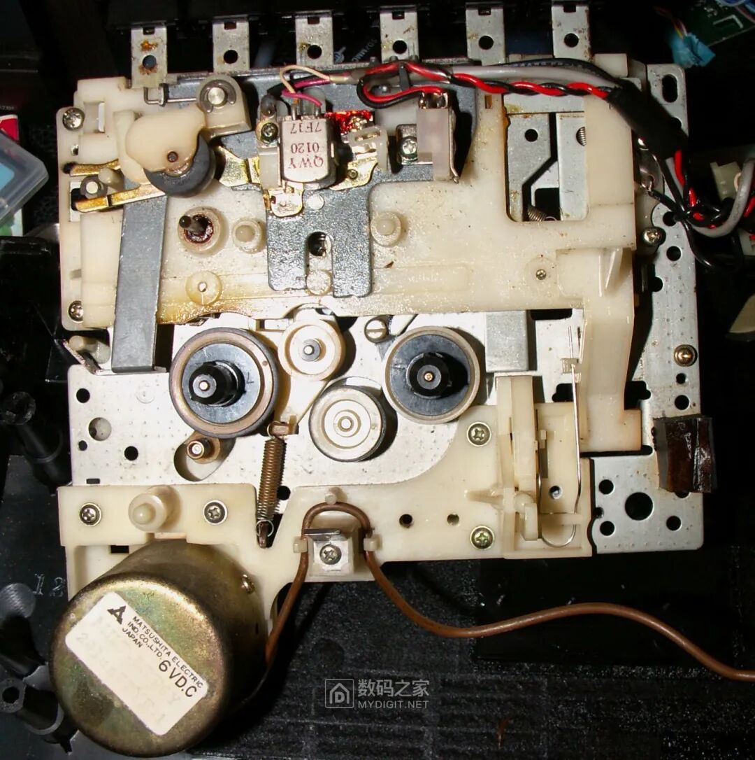 Completely remove the mechanism from the interior for maintenance:
 The bottom shell after completely removing the mechanism and circuit board: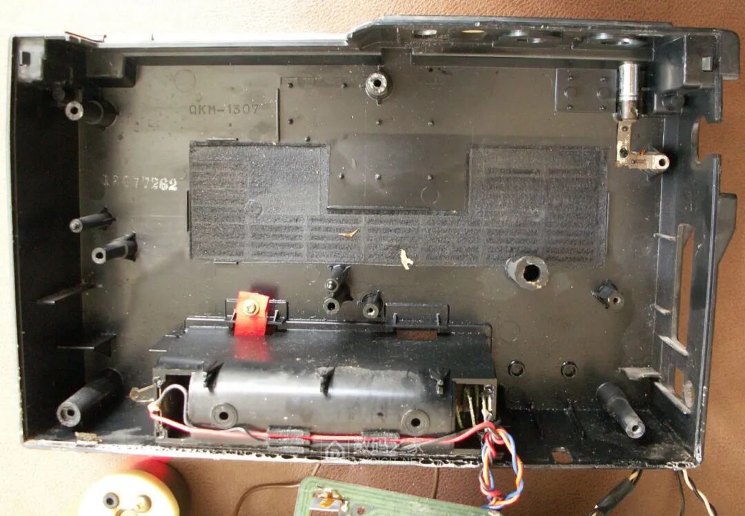
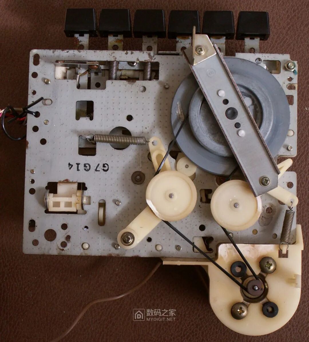
The main flywheel of the mechanism is made of all-metal, with a large diameter and weight, ensuring stable operation and reducing wobble. It is evident that the belt has aged and broken, requiring replacement: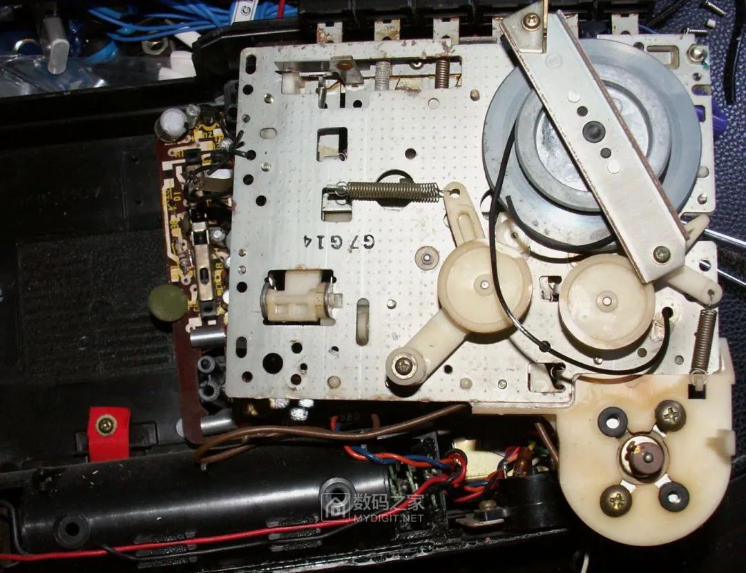
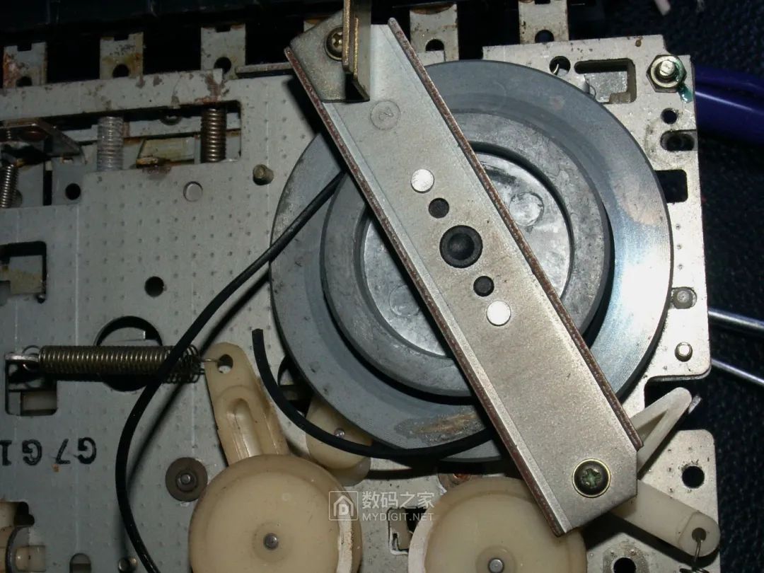
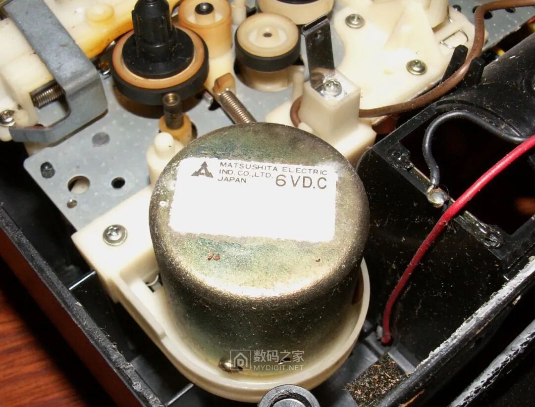
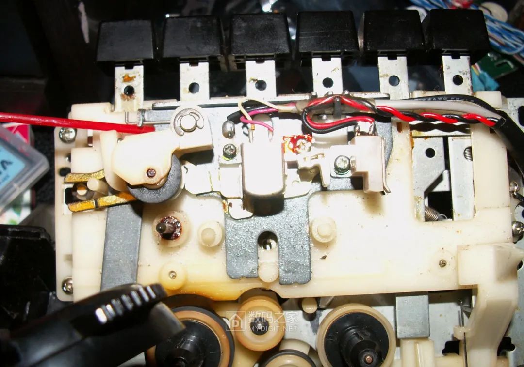
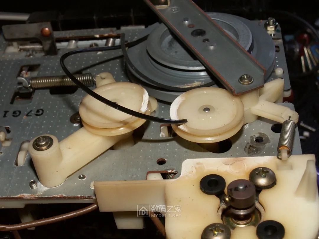 A close-up of the motor in the mechanism, which is quite large, is a Panasonic-produced 6V motor with a built-in speed stabilization mechanism (likely a mechanical centrifugal speed regulator, not an electronic speed control circuit):
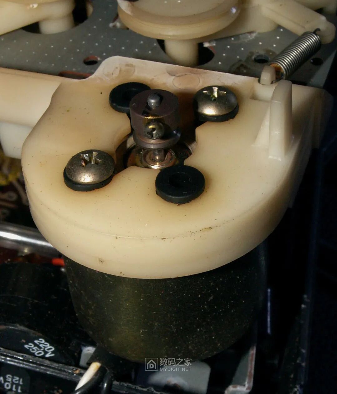
 A close-up of the motor’s metal pulley, which is secured to the motor shaft with screws, making the installation process complex. The motor is fixed to the mechanism with four rubber pads to reduce vibration:
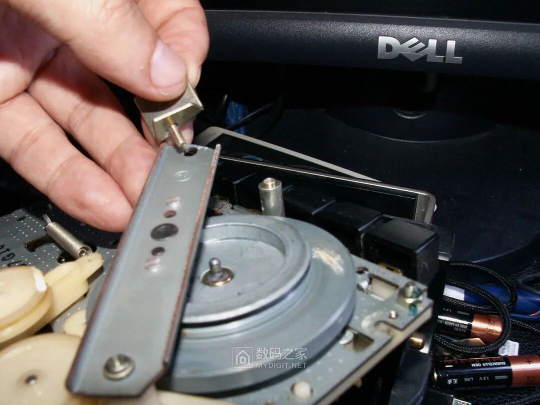
 Replacing the belt requires removing the main shaft fixing bar to thread in the new belt:
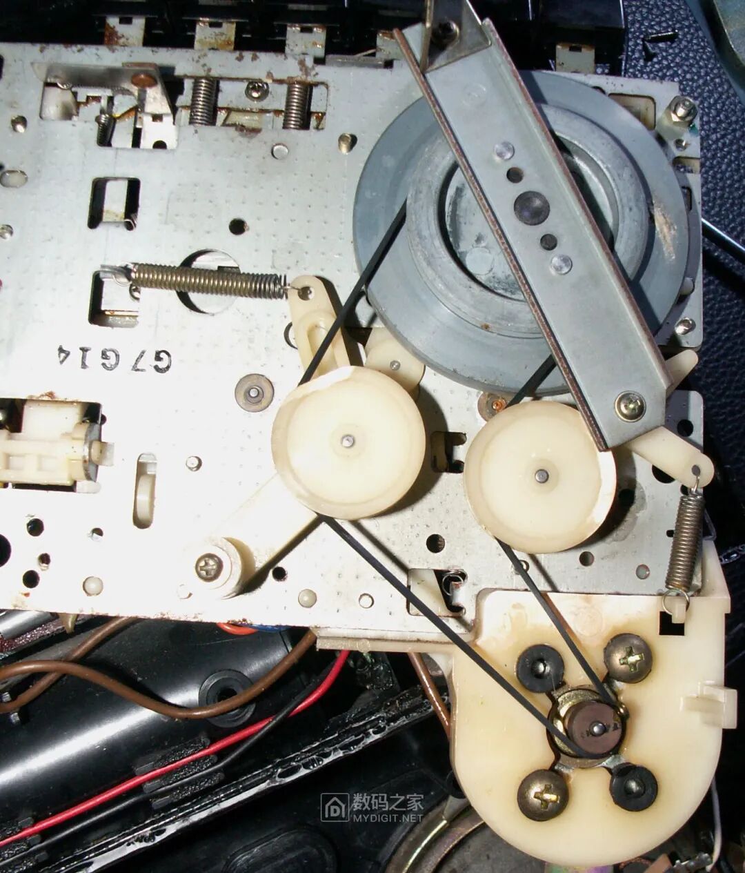
 The new belt installed:
 The issue with the mechanism buttons being stuck is easily fixed with WD40, which can loosen them. After spraying the relevant areas with the lubricant and repeatedly pressing the buttons, they quickly became responsive: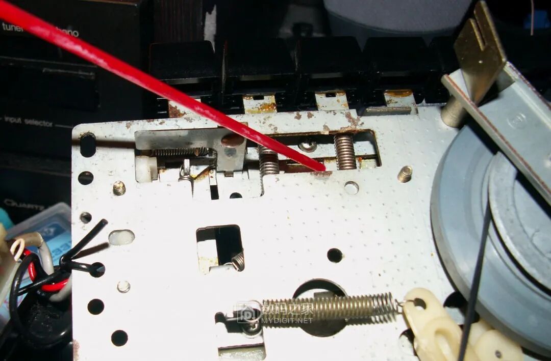
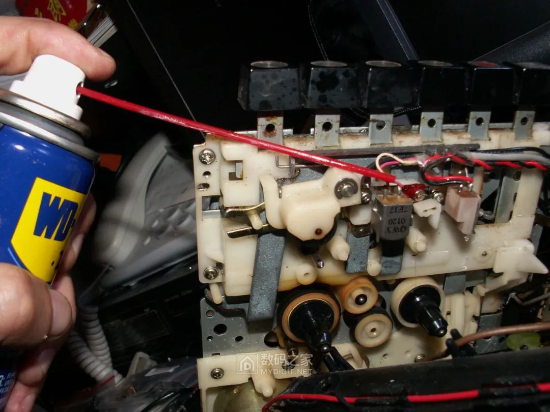
 The maintenance of the mechanism is complete, set aside for use:
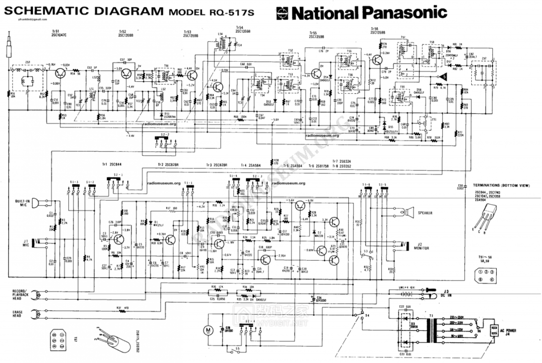
 Next is the maintenance of the circuit, which is much more complicated than the mechanism and has taken some detours. First, I found the circuit diagram for this machine online—only the circuit diagram was found, not the printed circuit board diagram, so actually comparing components and traces was quite labor-intensive. This tape recorder consists of 14 transistors, most of which are silicon, but the low-frequency section still mixes in 4 germanium transistors, which is quite unusual in the 1970s when silicon planar technology and even large-scale integrated circuits were already mature in Japan. Analyzing the circuit, it seems these germanium transistors were intentionally selected to take advantage of their extremely low saturation voltage characteristics to achieve greater output power and lower distortion at low supply voltages (6V), balancing the portability and performance specifications of this tape recorder. The entire circuit is quite mature and classic, with Tr51 as the FM reception amplifier, Tr52 responsible for FM local oscillator mixing, and Tr53 forming the first stage of FM intermediate frequency amplification. Tr54 is the local oscillator mixer for AM reception, then Tr55 and Tr56 simultaneously perform two stages of intermediate frequency amplification for both FM and AM, finally sending the signals to the AM diode demodulator and FM dual diode balanced demodulator to convert them into audio signals. Tr1~Tr3 perform audio pre-amplification, shared by reception and tape recording, Tr5 is an active filter providing stable power to the pre-amplifier circuit, and Tr7 and Tr8, a pair of complementary germanium power transistors, complete the output stage OTL push-pull amplifier output, while Tr4 and Tr6 provide stable bias current for Tr7 and Tr8 to reduce distortion.
 First, take a general look at the circuit board: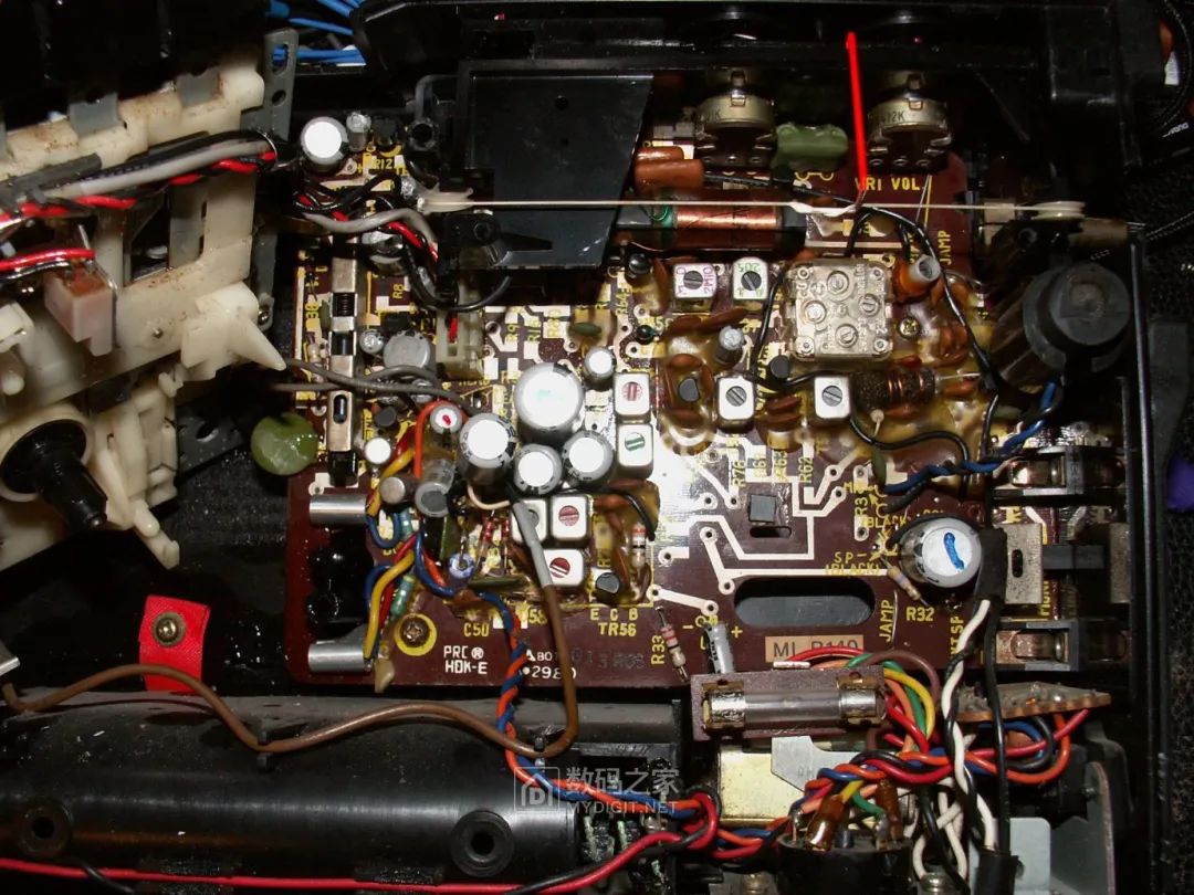
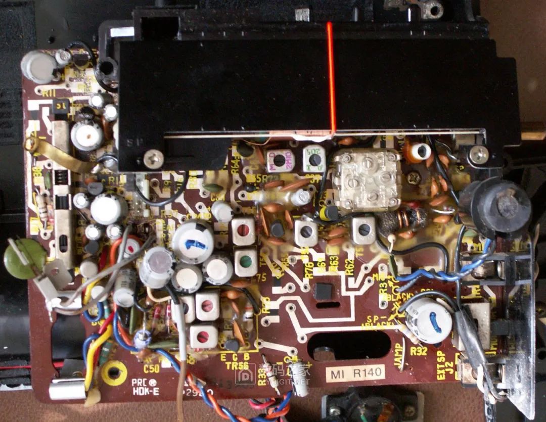
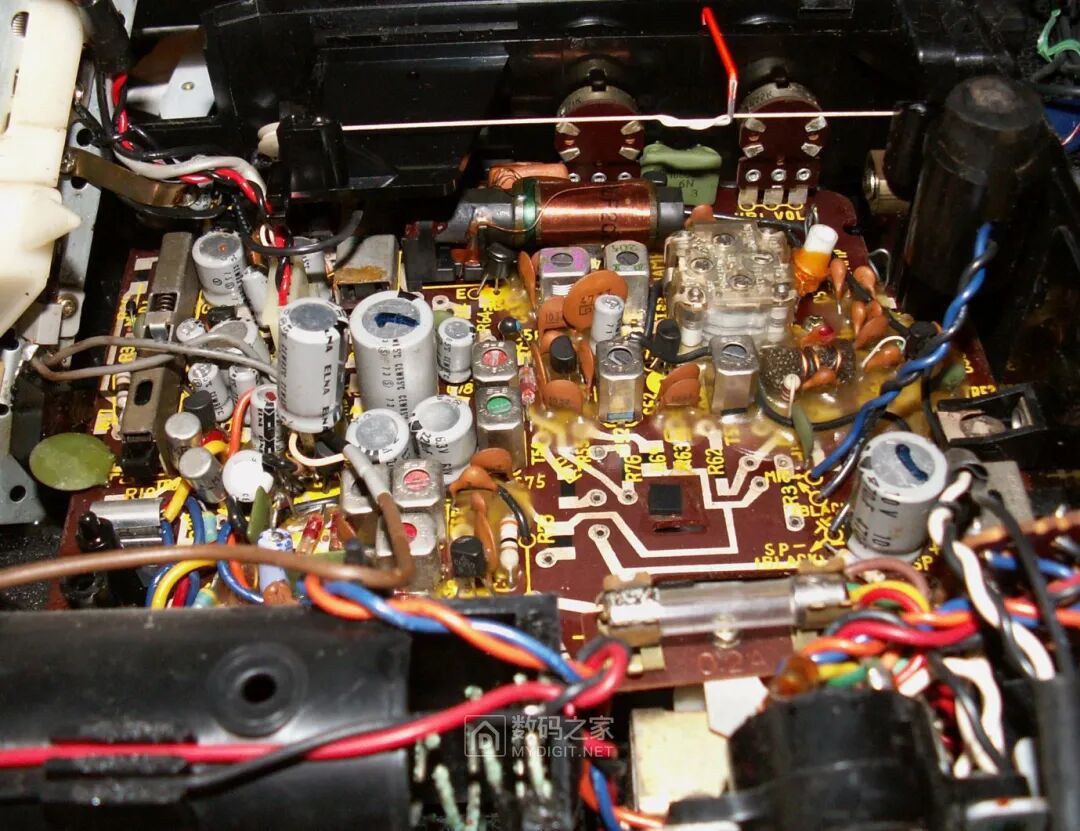
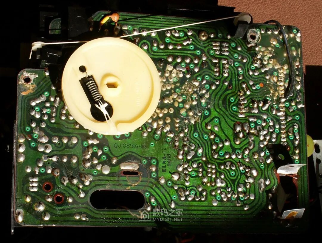
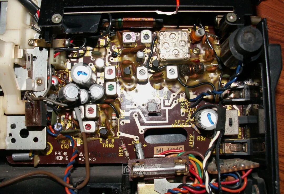
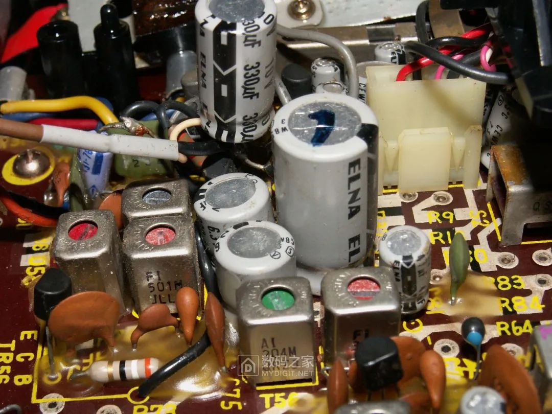
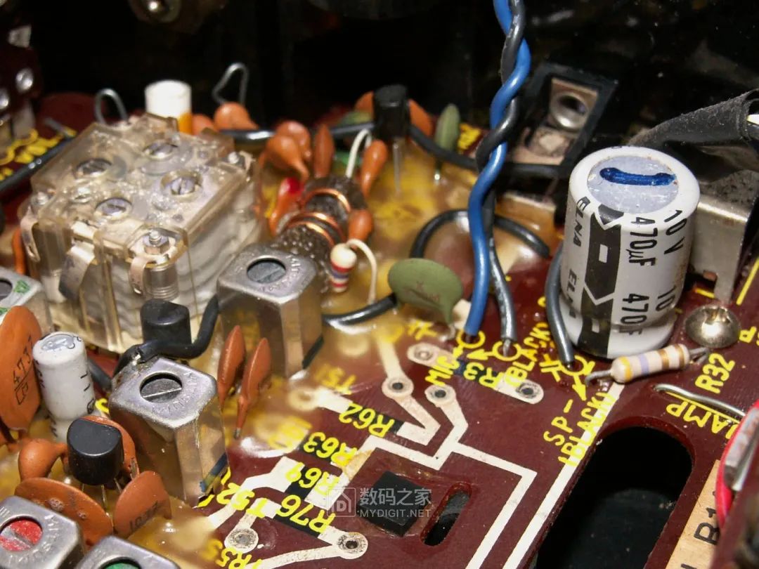
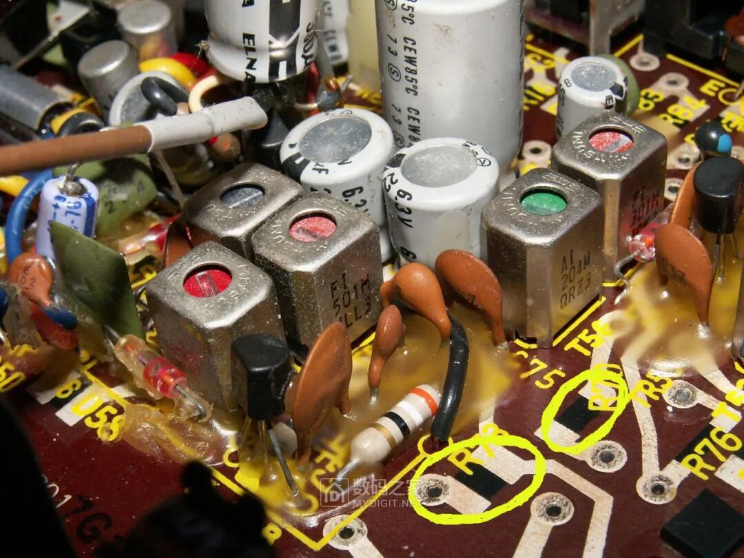
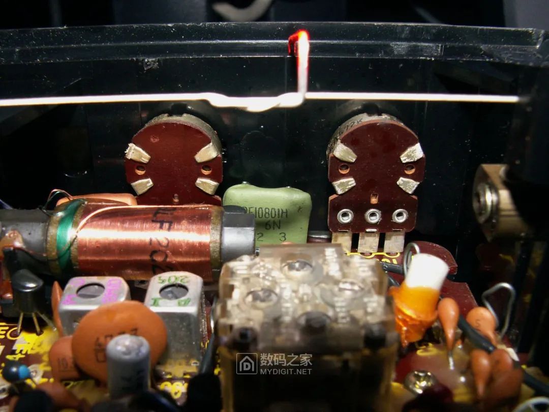 Some details on the circuit board are quite interesting and worth noting, such as the following. This circuit board is single-sided, but note that there is high technology on this single-sided circuit board—the white lines printed on the component side are not just copper foil traces but actual circuits, printed with silver paste to create another side of the circuit, thus achieving the flexibility of double-sided circuit board traces on a single-sided board. Moreover, this printing includes not only circuits but also components; note the yellow circled area, where the silkscreen indicates the resistor number, and inside the circle is a resistor directly printed on the circuit board with carbon film! This was high technology at the time, directly printing resistors onto the circuit board, reducing the number of soldered components and improving system reliability. This technology of directly printing circuits with silver paste and carbon film resistors on circuit boards was quite popular in the 70s and 80s in Japanese companies like Panasonic and Sony, representing high technology, but later fell out of favor due to production costs:
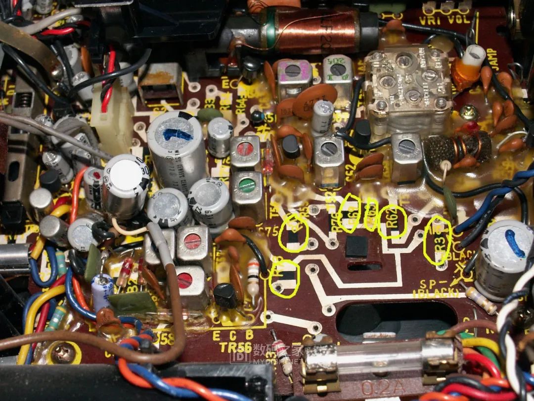 Looking closer, the carbon film printed resistor is clearer under close-up shots (circled area):
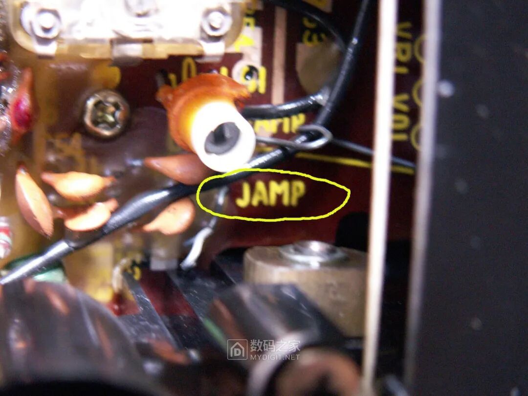
 Although the technology of using silver paste to print circuits on a single-sided board to achieve double-sided board performance has been employed, this circuit board still could not completely avoid the use of jumpers, and the Japanese engineer who designed this circuit board had some issues with English, as many of the jumper silkscreen labels were incorrectly spelled as “JAMP” instead of “JUMP” (circled area in the image):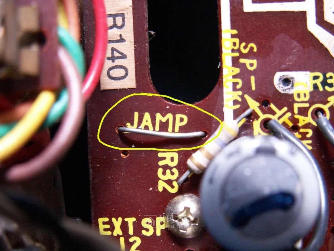
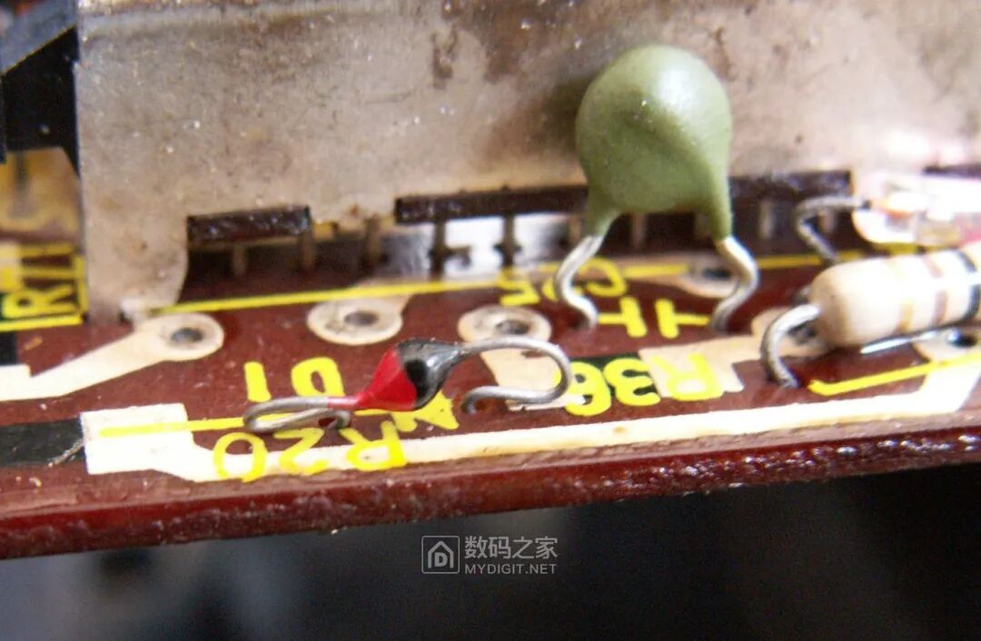
 The circuit board also shows some glass-encapsulated point-contact diodes, somewhat resembling the 2AP9 commonly used in Chinese crystal radios, except they are not painted black: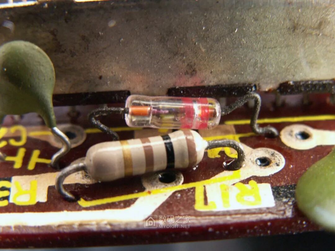
 More interestingly, several metal-encapsulated medium and small power germanium transistors (indicated by the arrows in the image) are quite common in old radios in China, but should be very rare in Japanese products from the mid-1970s. The use of germanium transistors was previously analyzed to enhance the amplifier’s distortion-free output power at low voltages:
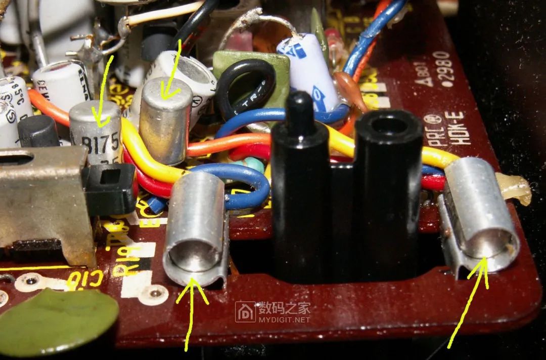 Two of the output power germanium transistors are wrapped in aluminum sheets to help dissipate heat:
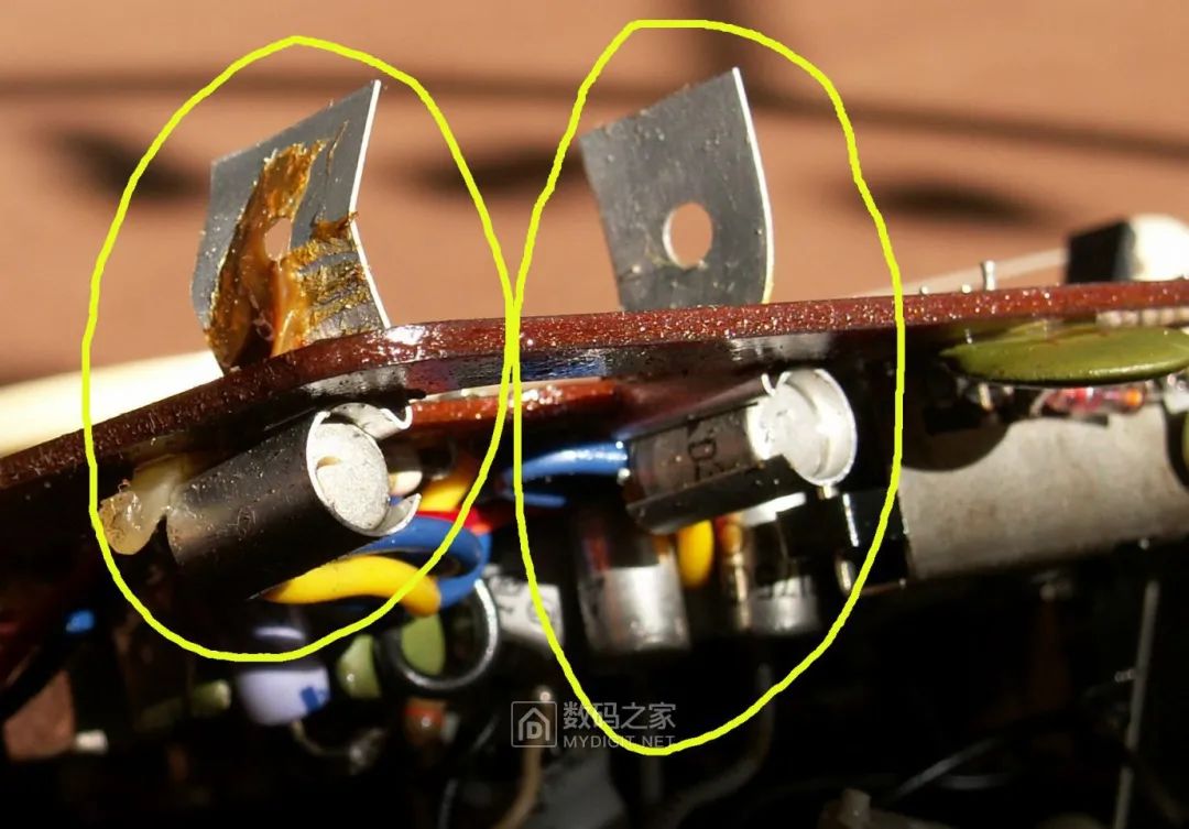 Taking one of the power transistors out of the heat-dissipating aluminum sheet, it is not directly soldered to the circuit board but connected via soft wires: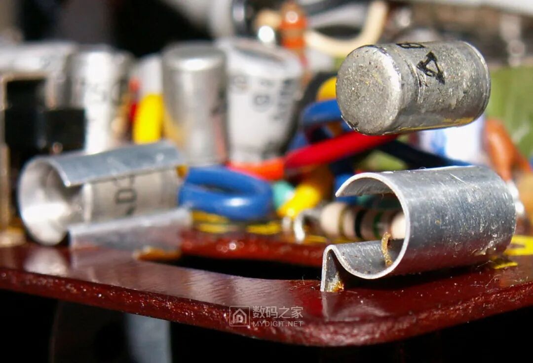
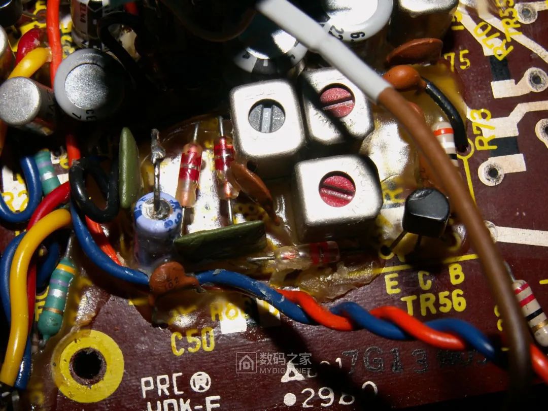
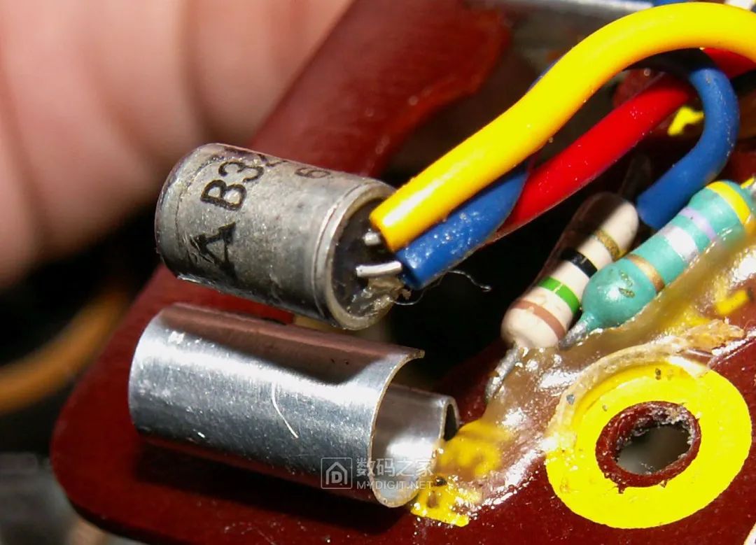 Even more bizarre, despite the use of high-tech circuit boards, some components are still soldered using a makeshift method, such as this electrolytic capacitor (this was how it was originally designed, not due to repairs):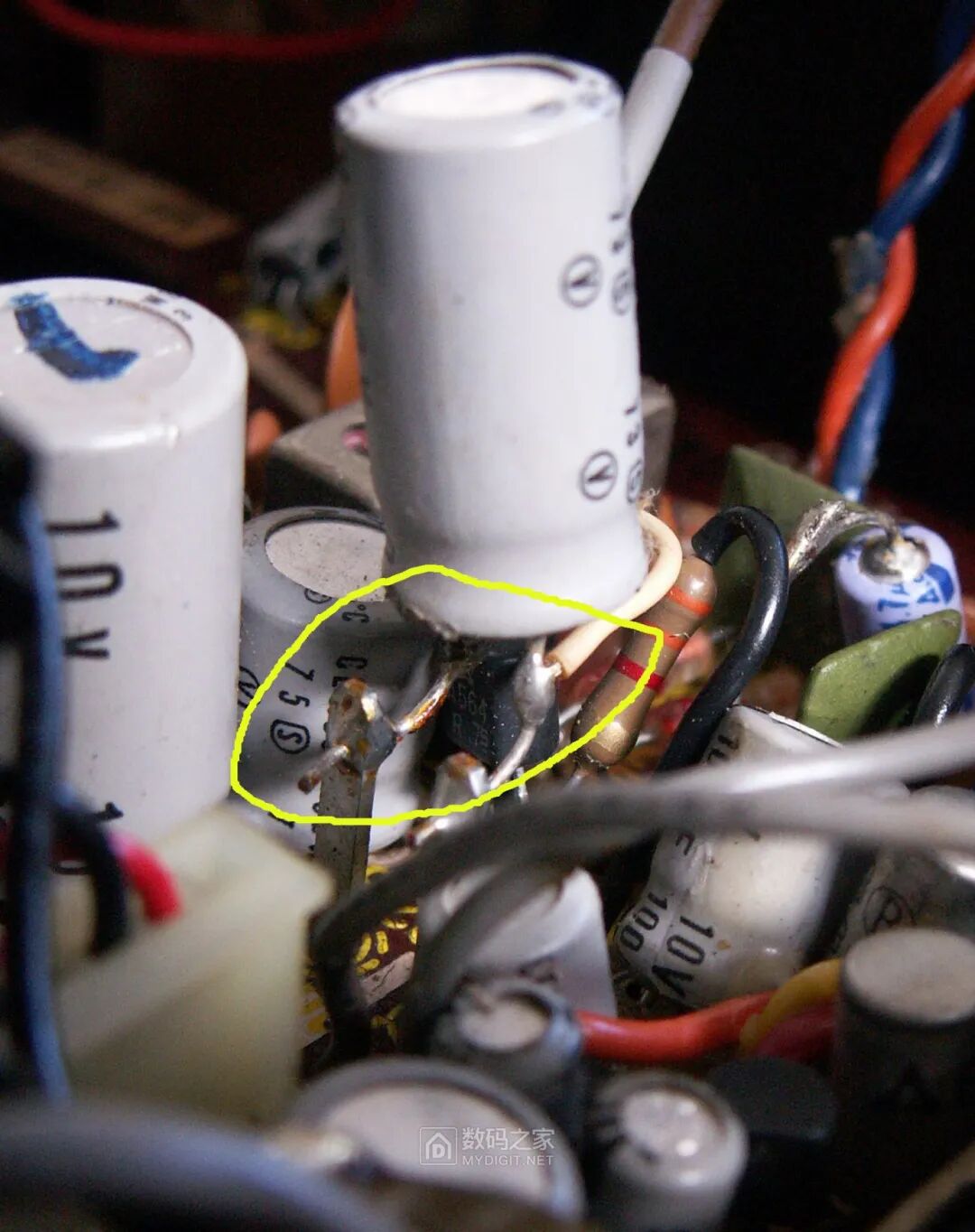
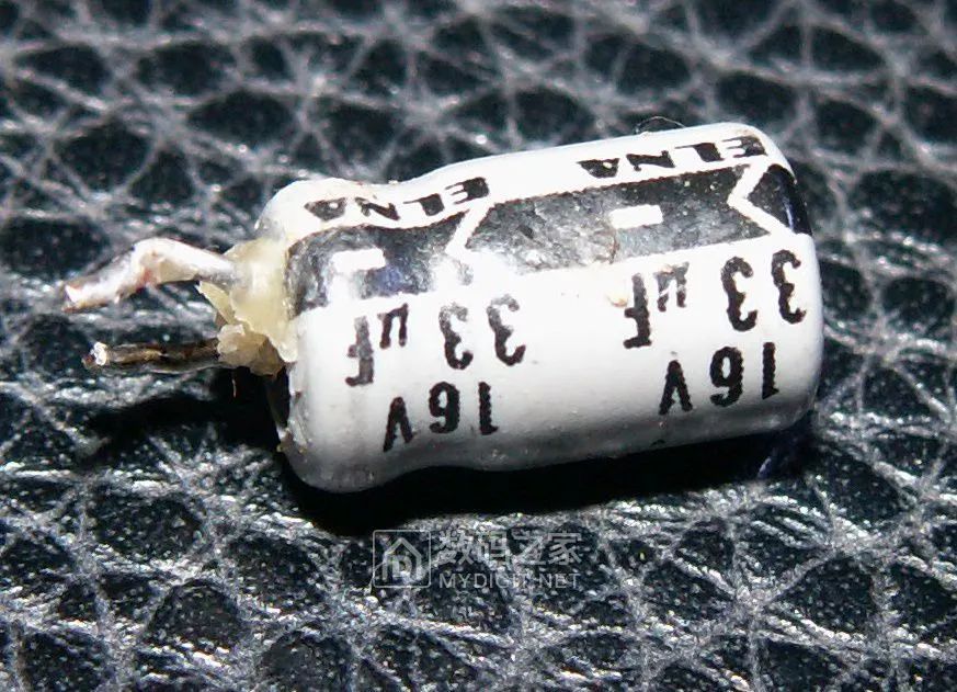
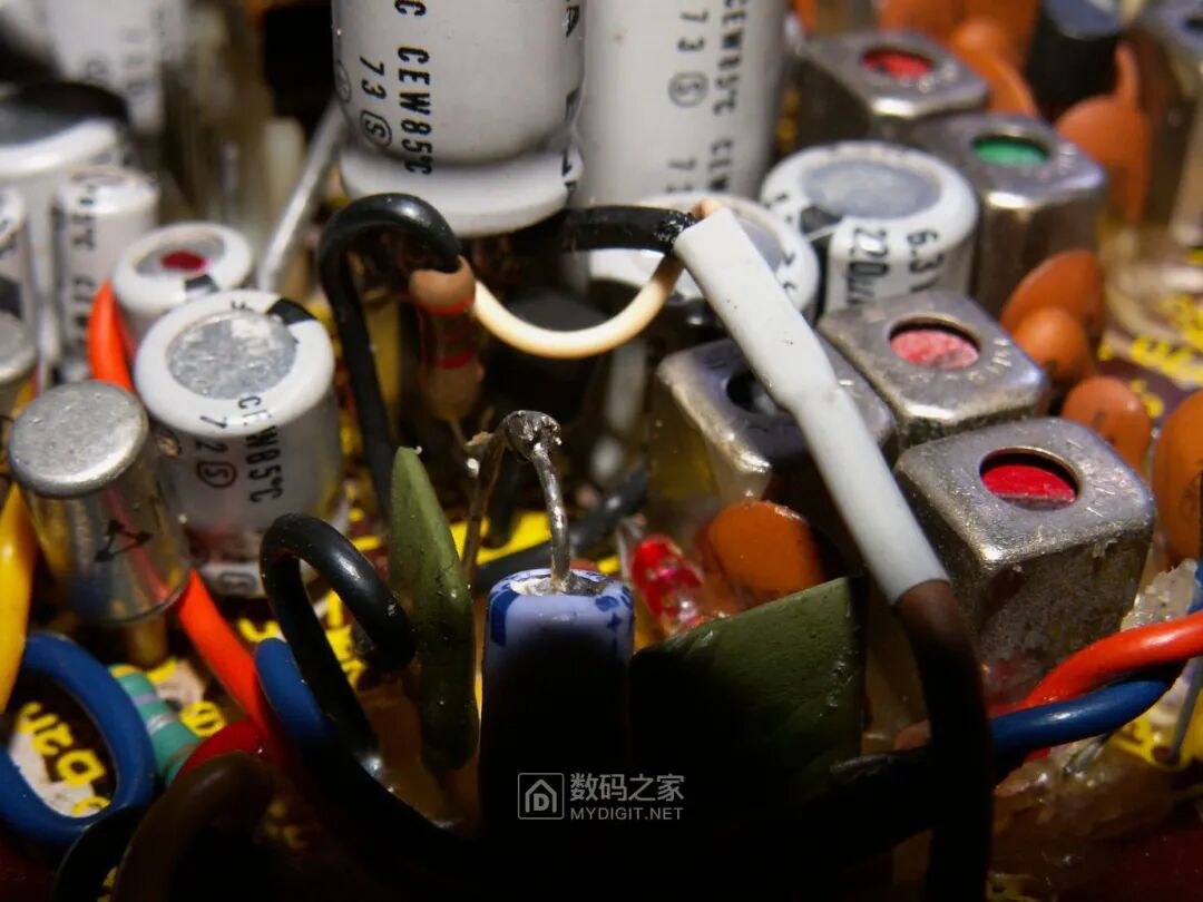 Now begins the arduous repair. The fault symptom is a clicking noise, so according to common sense, the first suspicion falls on the nearly 50-year-old electrolytic capacitors that might have failed. However, upon testing the capacitors, it was surprisingly found that their capacitance values were all within the specified range, and half a century of aging had not diminished their capacity. No wonder, as even the smallest electrolytic capacitors used are from ELNA, a high-end brand, very reliable:
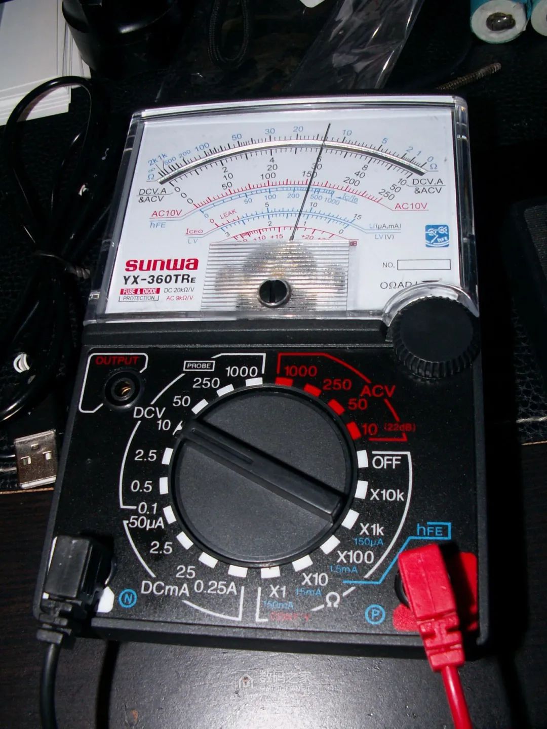
 Using a pointer multimeter connected to the power supply of the audio pre-amplifier circuit, I found the voltage was unstable, fluctuating:
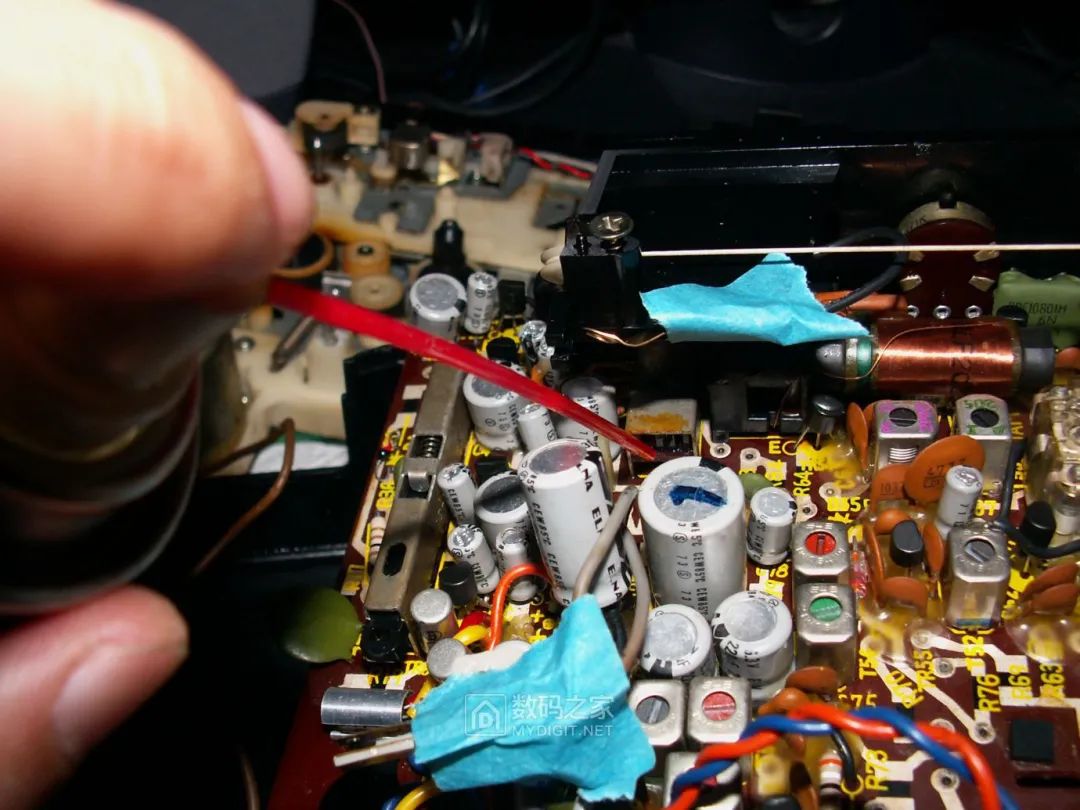
 Therefore, I suspected that Tr5, the active filter circuit, might be problematic. After searching the circuit board for a long time, I finally found the position of Tr5, and it appeared to be soldered in a makeshift manner:
 :
: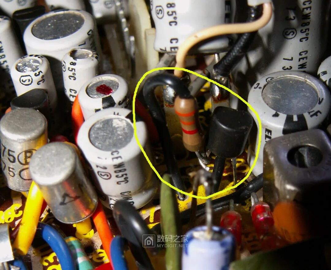 After removing it, it turned out that this component was soldered together with a resistor and then soldered to the circuit board. I wonder what the designer was thinking back then; they used high-tech silver paste printed double-sided circuit boards, yet still employed makeshift soldering techniques in several places. It seems that during mass production, some circuit modifications and improvements were made while the circuit board had already been finalized:
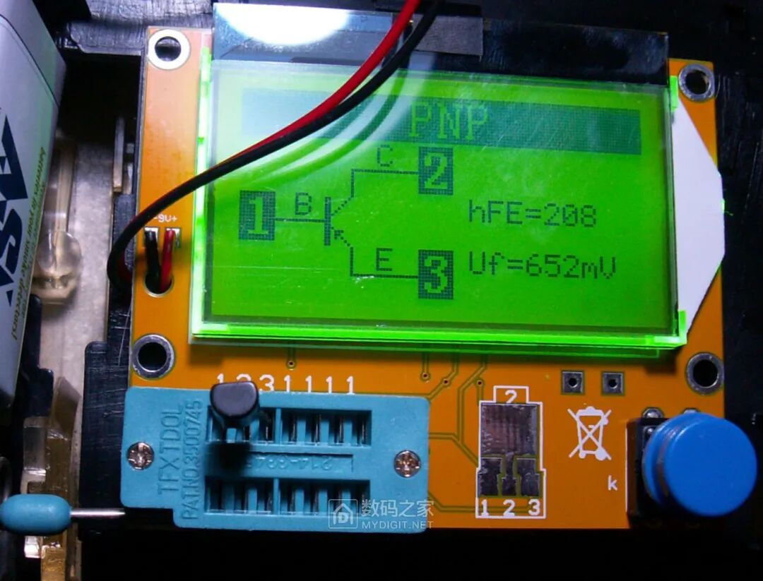
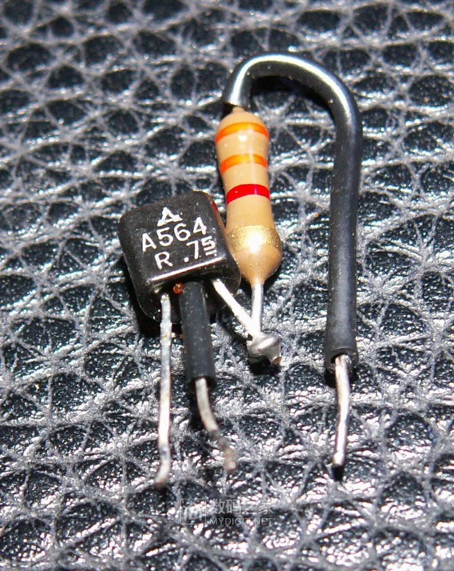 However, this transistor tested fine, with an hFE of 208, which was quite good for the craftsmanship level in the 1970s:
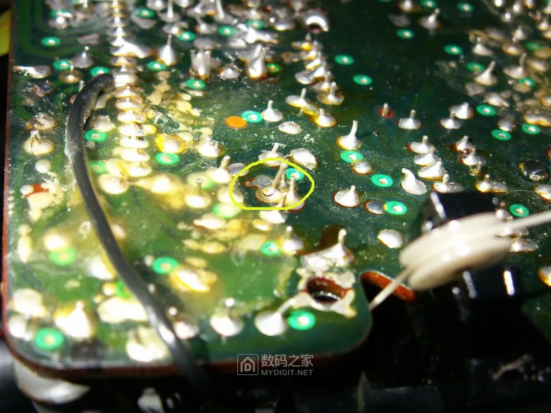
 Next, the repair hit a dead end. The inspection results showed that the electrolytic capacitors were not aging, and all transistors were functioning well, so where was the problem? While flipping the circuit board over and over to find the issue, suddenly the noise unexpectedly disappeared, and the radio sound appeared! Then a few seconds later, the noise returned, and the radio sound vanished. This was a good sign, indicating that the problem was likely due to a cold solder joint on the circuit board. Using a magnifying glass to carefully inspect the soldering side of the circuit board, I indeed found this cold solder joint, indicated by the circled area:
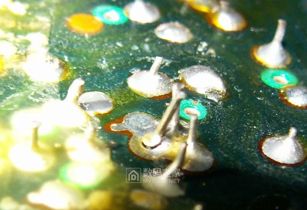
 Zooming in makes it clearer:
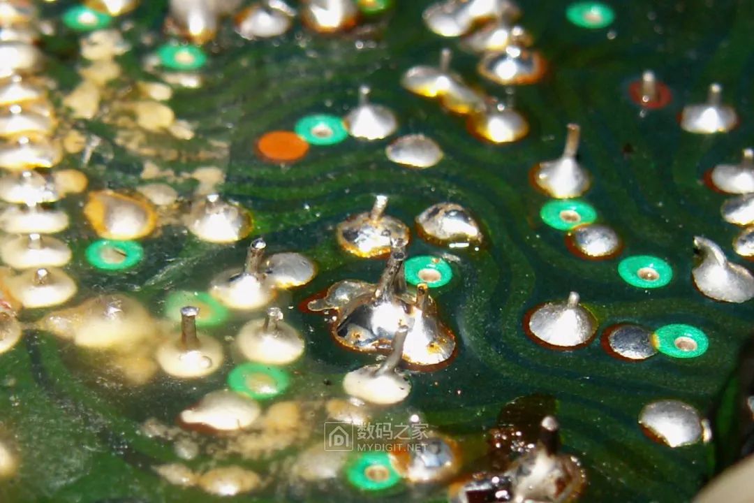
 After re-soldering this cold joint, the fault was resolved:
 After soldering, testing the machine revealed clear broadcast sounds, bringing immense joy! Next, I found that switching the function selector and adjusting the volume also produced noticeable noise. I once again used WD40 to spray all the switches and potentiometers, and the noise disappeared immediately:
 Finally, after assembling the entire machine for a complete test, I found that this nearly 50-year-old tape recorder was in remarkably good quality and condition, especially the FM reception sensitivity, which was extremely high, even surpassing that of various newer integrated circuit radios I had on hand. Achieving this sensitivity with just a few discrete transistors, and after decades, the components’ parameters had not drifted or degraded, indicating a high level of design and component craftsmanship. The AM performance was acceptable, but with so much interference on the AM band nowadays, it was basically unlistenable. Surprisingly, this compact portable unit produced very loud sound at high volume without noticeable distortion, likely due to its specially selected germanium transistor output stage and the custom 3.2-ohm low-impedance speaker. The tape playback quality was rather average, with somewhat muffled sound and only mono output. The recording quality was even poorer, as it was the simplest DC erase and DC bias magnetic recording design, with recording being merely an auxiliary function. Aside from a broken rubber belt, all other components, including the most failure-prone electrolytic capacitors and ceramic capacitors in the intermediate frequency section, were completely normal with no issues. Panasonic’s component quality control back then was indeed quite reliable. Of course, fixing this nearly half-century-old machine has little practical value; no one would really use this antique daily for listening to broadcasts or tapes. The motivation to repair it stems from a sense of nostalgia and respect, to learn from the past and engage in a dialogue with time and classic craftsmanship.
Source: Digital Home