In the last article, we explained the major categories of sensors and waveforms. Today, we will discuss the waveforms of actuators and the CAN bus.
01Ignition Waveform
Working Principle:
When the ECM controls the primary (low voltage) winding, the primary winding magnetizes the core (charging) and stores it;
When the primary winding is disconnected, as the current in the primary winding disappears, the core begins to demagnetize, causing the magnetic field lines to cut through the secondary winding, generating a very high induced voltage in the secondary (high voltage) winding, which is delivered to the spark plug to ignite the mixture.
At the same time, while the core demagnetizes, it also cuts through the primary winding, generating an induced voltage.
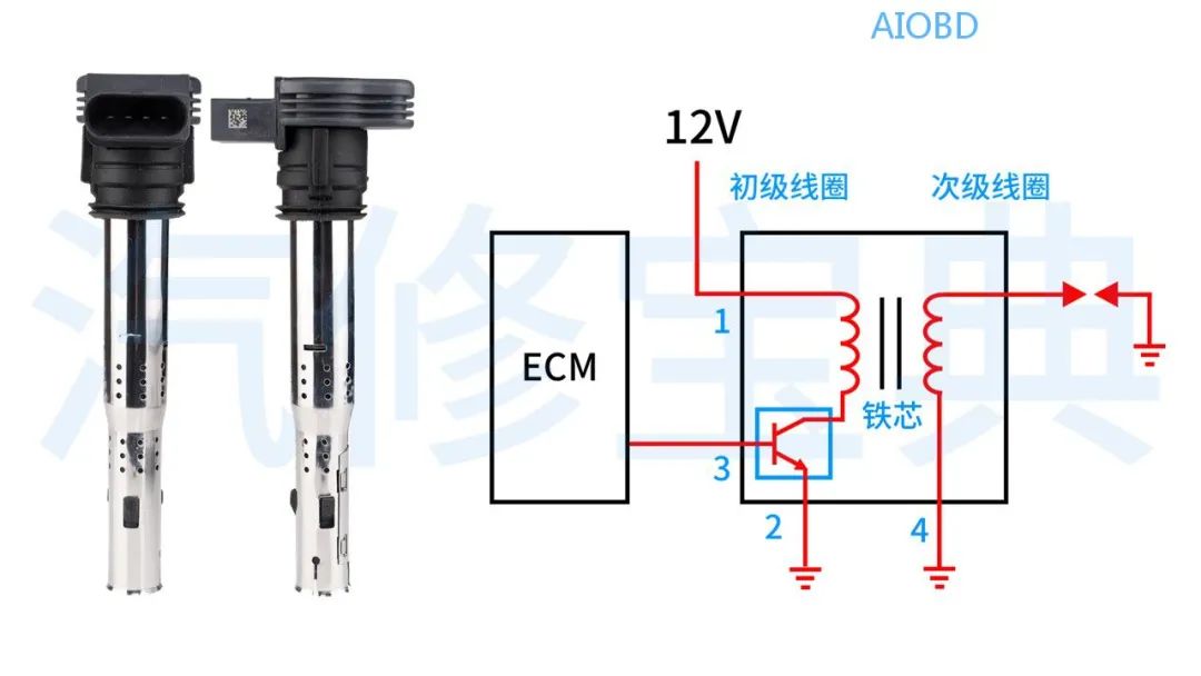
Real Vehicle Waveform:
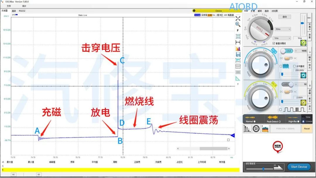
This is a secondary ignition waveform. In the diagram:
Point A: Power transistor closed (charging)
Point B: Power transistor opened (discharging)
Point C: Breakdown voltage
Point D: Combustion starts
Point E: Combustion ends
Waveform Analysis:
1. Check Breakdown Voltage
The breakdown voltage varies with different vehicles; it is recommended to compare multiple cylinders.
Too Low: Spark plug gap too small, low resistance of high voltage wire, rich mixture
Too High: Spark plug gap too large, high resistance of high voltage wire, lean mixture
2. Check Combustion Line
Excessive noise in the combustion line indicates unstable combustion in the cylinder.
Lean mixture increases breakdown voltage, while combustion voltage D decreases.
Rich mixture decreases breakdown voltage, while combustion voltage D increases.
Carbon buildup or dirt on the spark plug will cause the combustion line to tilt significantly.
3. Check Combustion Time
Generally, the combustion time (as shown in the above diagram D-E) is greater than 2ms for a rich mixture and less than 0.75ms for a lean mixture.
4. Check Oscillation Count
At least 2 oscillations are required.
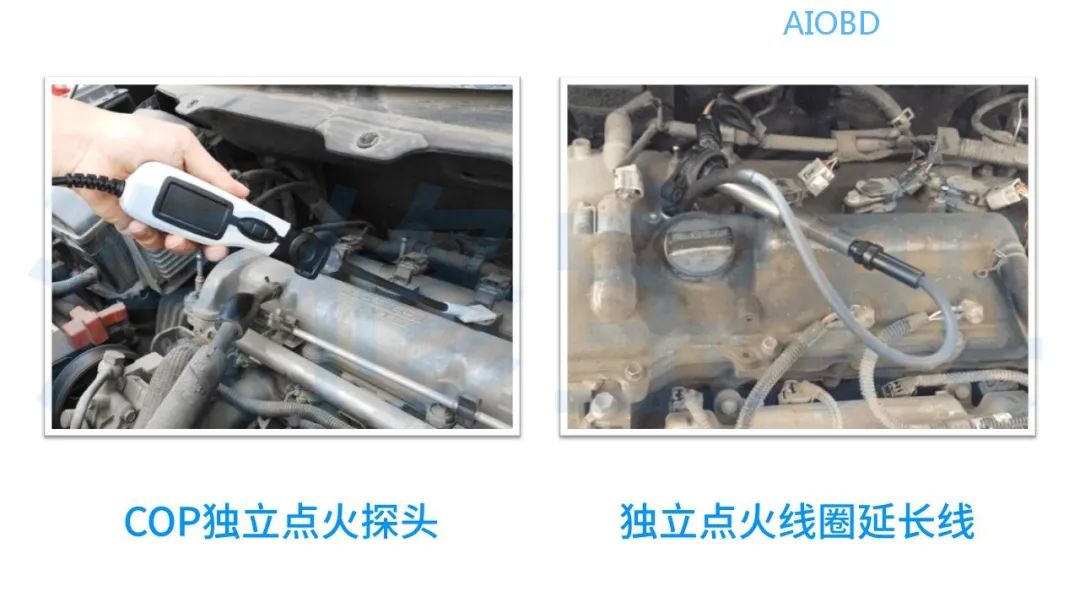
PS: COP stands for Coil-On-Plug, which refers to independent ignition coils.
02Fuel Injection Waveform
Working Principle:
The fuel injector is an electromagnetic valve. When powered, the coil generates a magnetic field that lifts the needle valve, opening the injector; when powered off, the magnetic field disappears, and the injector closes.
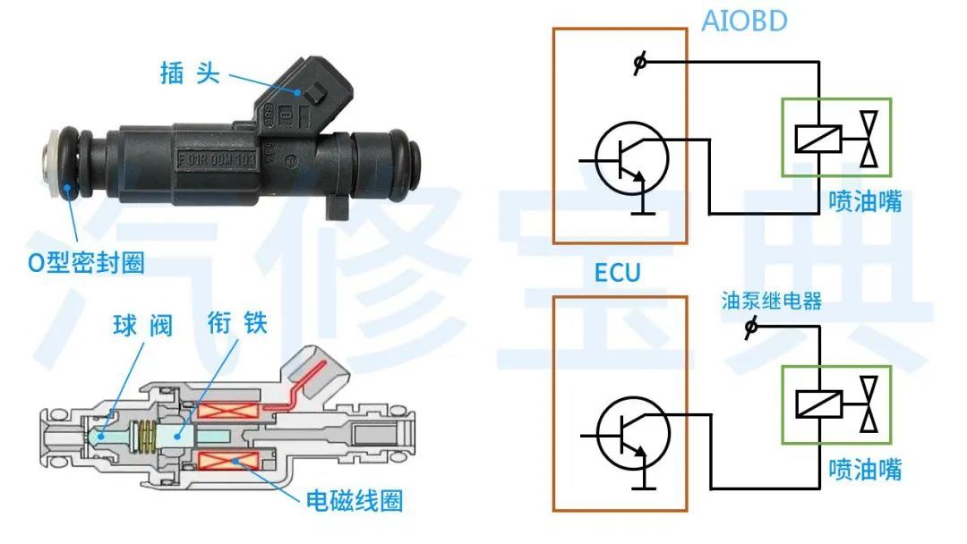
Real Vehicle Waveform:
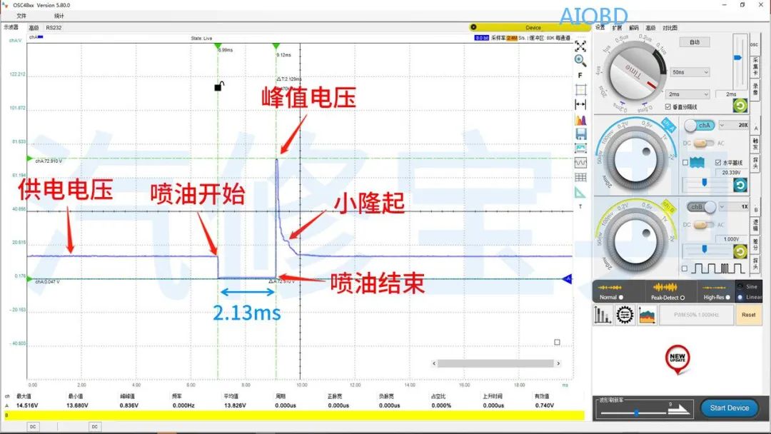
This is the fuel injection waveform of a saturated switch type injector. From the diagram, we can see:
The pulse width of the fuel injection is 2.13ms, and the peak voltage generated by the decay of the coil’s magnetic field is 72.9V.
Waveform Analysis:
1. Check Fuel Injection Pulse Width
After the engine warms up and enters closed-loop control, the pulse width reflects the richness or leanness of the mixture.
2. Check Peak Voltage
It is related to the current flowing through the injector coil and the number of turns in the coil; generally, the peak voltage should not be less than 35V.
3. Check Small Bump
This small bump is caused by the return of the injector valve needle and should not be absent.
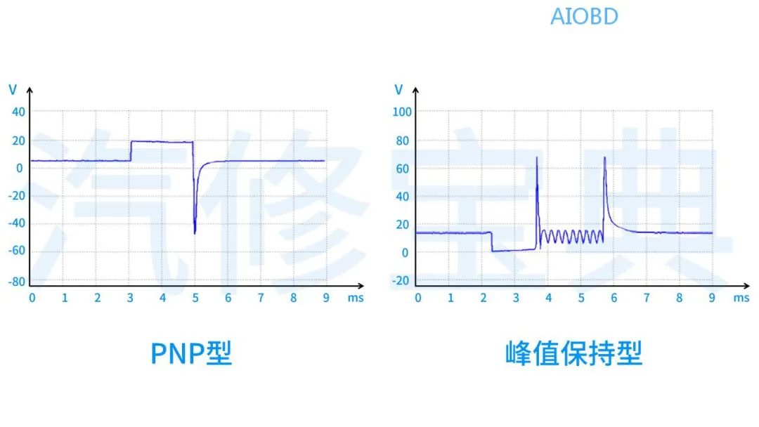
In addition to the above-mentioned saturated switch type, there are peak holding type, pulse width modulation type, and PNP type injectors.
03Valve Body Waveform
Working Principle:
Like the fuel injector, it is controlled by energizing the coil to position the valve core to achieve a specific purpose.
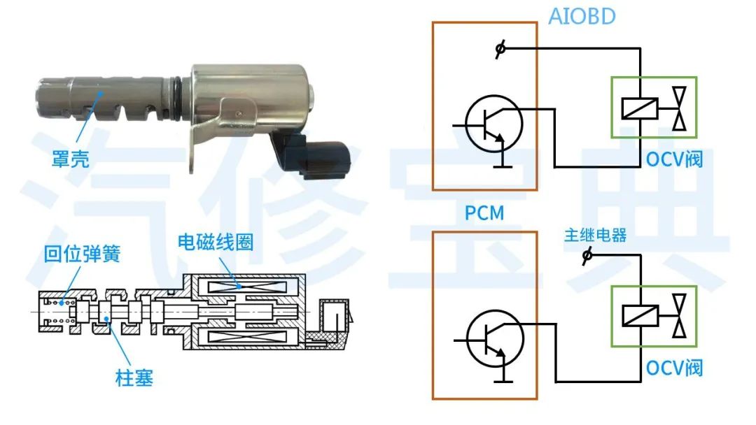
PS: OCV stands for Oil-Control-Valve, which refers to the oil control valve.
Real Vehicle Waveform:
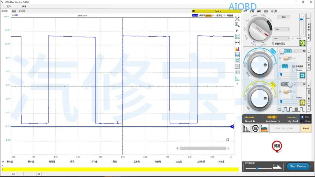
This is a duty cycle control waveform of the OCV valve in the VVT system.
Waveform Analysis:
Focus mainly on its amplitude and frequency; the frequency of the OCV valve is related to the engine speed.
PS: Duty cycle control is used not only for controlling the flow of valve bodies but also for controlling the brightness of lights, fan speed, etc., and the waveforms are similar.
04CAN Bus Waveform
Working Principle:
The CAN bus is a serial communication protocol where multiple modules are connected to a single CAN network. When a certain (module) node sends signal data to the CAN network, the other (module) nodes will receive this data and analyze whether it is needed.
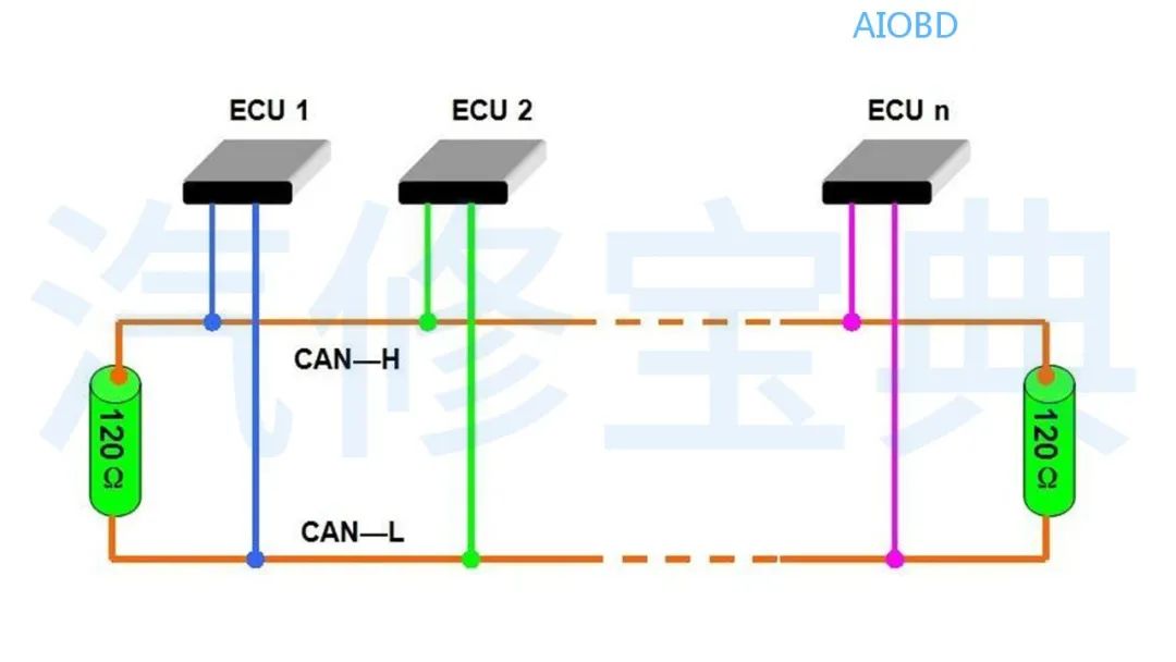
The CAN bus uses twisted pair cables as the bus medium, transmitting data via differential signals, mainly including drive CAN, comfort CAN, and infotainment CAN.
Real Vehicle Waveform:
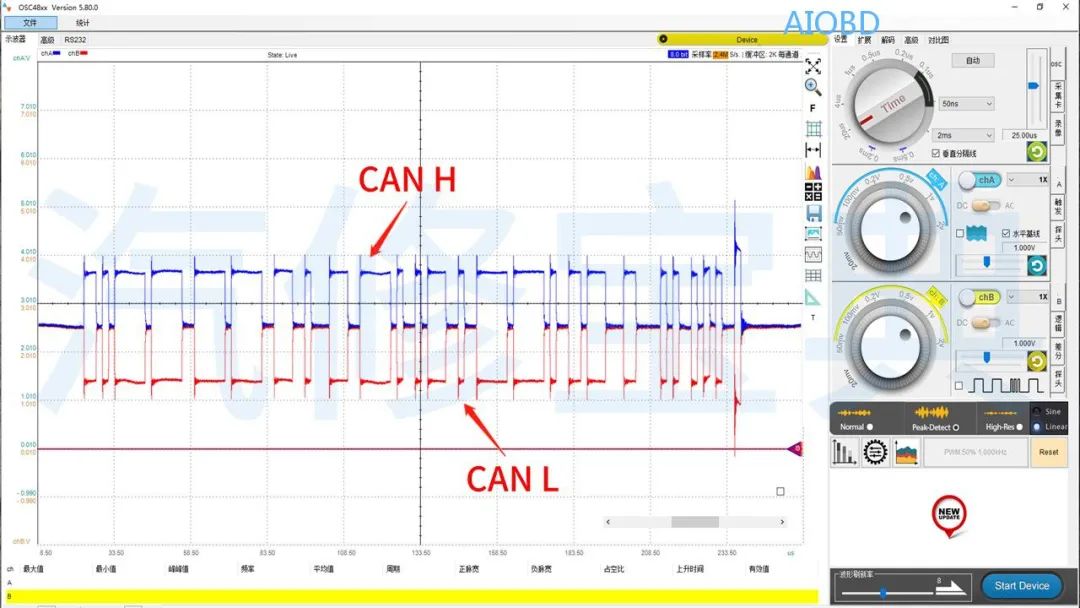
From the above diagram, we can see that the waveforms of CAN H and CAN L are consistent, with opposite polarities, being symmetrical.
Waveform Analysis:
First, we need to know the voltage situation of the bus.
From the diagram, we can see that for this (Volkswagen) model, the voltage driving the CAN bus is approximately CAN-H’s dominant voltage of 3.5V, recessive voltage of 2.6V; CAN-L’s dominant voltage of 1.5V, recessive voltage of 2.4V.
When analyzing the bus waveform, we can also use the oscilloscope’s built-in logic operation function to calculate and judge its differential and common-mode signals.
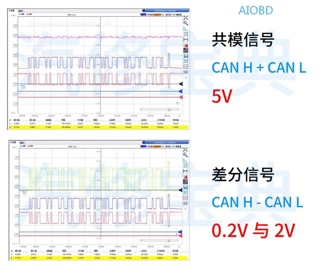
PS: For Volkswagen models, the voltage for comfort CAN is approximately CAN-H’s dominant voltage of 3.6V, recessive voltage of 0V; CAN-L’s dominant voltage of 1.4V, recessive voltage of 5V.
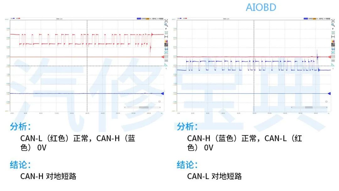
Knowing the normal voltage situation allows us to analyze bus faults effectively. Here are some bus faults to share.
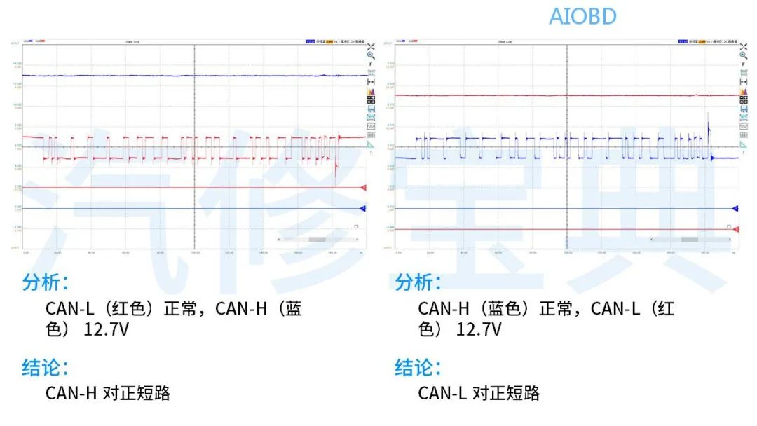
1Positive Short Circuit
PS: If both are 12V, then it is a simultaneous positive short circuit.
2Ground Short Circuit
PS: If both are 0V, then it is a simultaneous ground short circuit.
3Mutual Short Circuit
If the waveform signal voltages are the same and the waveforms tend to be consistent, then CAN-H and CAN-L are mutually short-circuited.
4Open Circuit
If one of CAN-H or CAN-L is normal while the other approaches a straight line, but there are response signals from other control units, it indicates that the CAN-H or CAN-L is open-circuited.
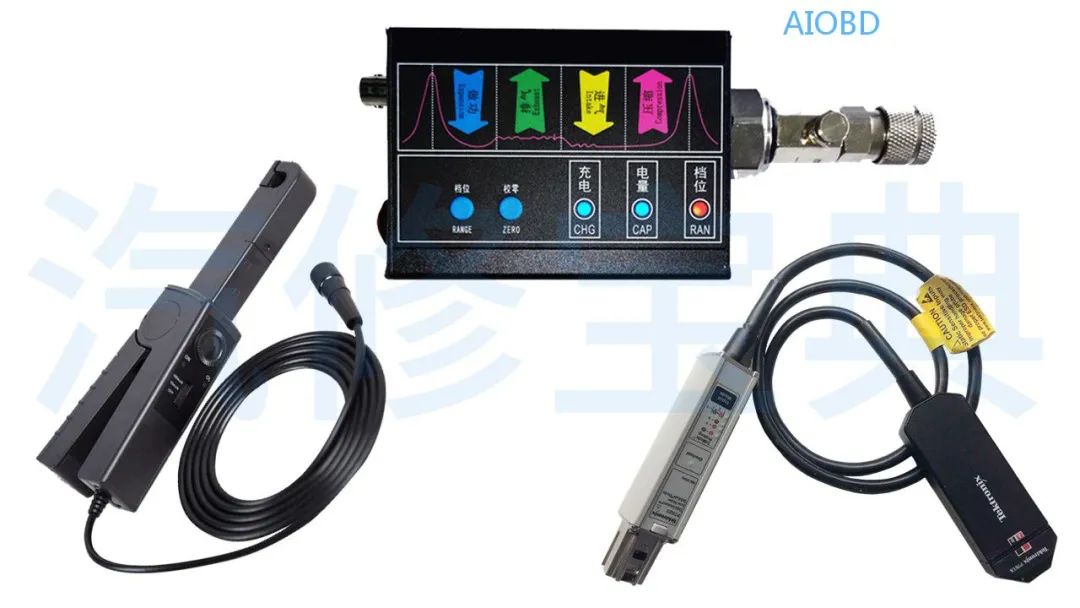
In addition to the basic measurement of sensor, actuator, and bus (voltage) waveforms mentioned earlier, we can also use other accessories to measure current, pressure, noise, and vibration, etc.
Alright, this concludes our discussion on the relevant knowledge of oscilloscopes.
If you want to learn well, you should measure, analyze, record, and compare normal waveforms during daily maintenance.