Source: Chuxin Jilv, Author: Chuxin Jilv
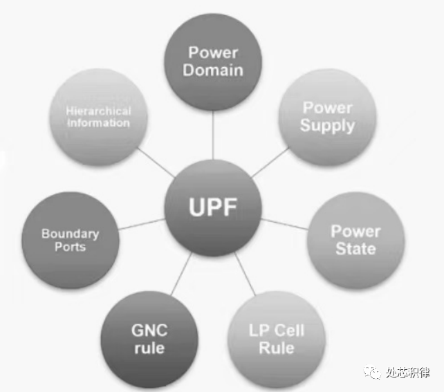
Figure 1: UPF file includes/defines the content of low power design
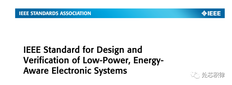
In fact, UPF focuses on describing and defining the chip power architecture (such as voltage source definitions, power state definitions, connections of low power cells ISO, MTCMOS (PSW), LVL, ELS cells, power supply relationships, and layout information). The UPF file, like the SDC file, has its own writing style. UPF has long been recognized as a standard protocol, and backend engineers who have done low power design should know that when importing UPF 3.0 in Innovus, the file is not called UPF but IEEE 1801. The following figure shows the UPF usage standards, which can be seen as the IEEE low power design standard, including the man page for UPF commands and usage notes.
Basics of UPF Encoding (Content: Power network definition, multi-voltage domain design, low power modes, low power cell rules, chip edge power definitions, IP power descriptions)
In fact, UPF runs through the entire backend design. Different voltage domains use corresponding library cells (including various .lib total libraries), for example, 1.0V uses a 1.0V library and 2.0V uses a 2.0V library. In synthesis, ISO, ICG, and LEVEL SHIFTER are generally added, while SWITCH_cell (MTCMOS four-pin chain) is added in physical design. It is also worth noting that low power cells are generally added at the boundary of the power domain, but if some low power cells (ISO, level shifter) are added on the pins of the macro, they cannot be placed at the voltage domain boundary. CLP verification mainly checks whether the UPF architecture (those contents) is correctly written, implemented through Cadence’s Conformal tool, while Tempus and Voltus are Cadence’s PT and PI signoff tools.
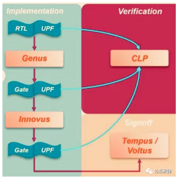
Figure 2: UPF full process in backend and signoff CLP, PI verification process
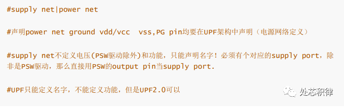
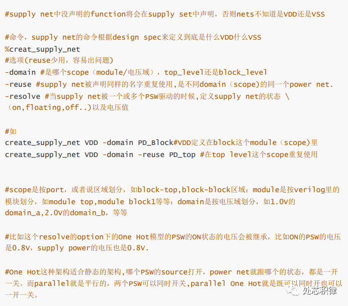
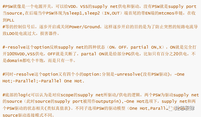
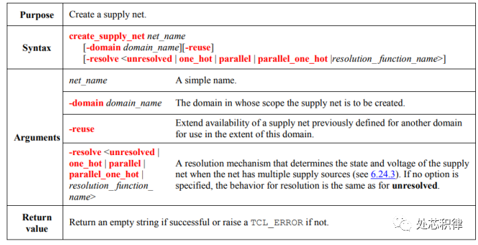
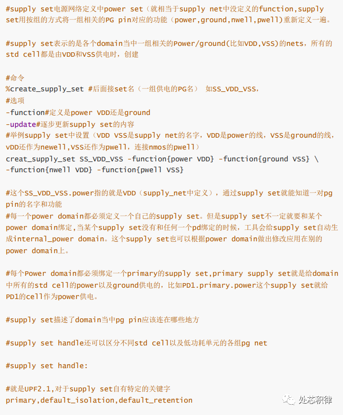
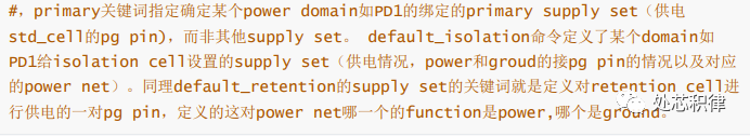
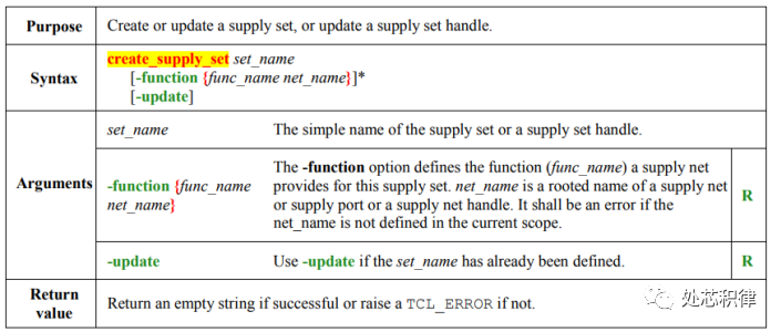
UPF supply network definition supply net
UPF supply network definition supply set
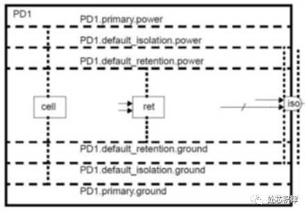
The figure shows that the supply set of PD1 includes primary power supplying the internal elements and the always-on PG net supplying ISO and retention.
At this point, I have introduced the general content of UPF encoding and its application process in the backend, as well as two important UPF create commands: supply_net and supply_set. Next time, I will take an example of a multi-PD module’s UPF to explain in detail and step-by-step the writing rules of UPF, making it easier for engineers to write UPF low power files. Engineers can also use UPF to plan power networks and voltage domain supplies for their project modules.
Recommended Reading:
-
Digital IC Low Power Design
-
Low Power RTL Design Optimization: Reduce Your Design’s Power Consumption!
-
Top Global Chip Experts Reveal the Truth About Low Power Chip Design
-
ASIC Design Learning Summary: Overview of Low Power Design and Book Recommendations