Edge detection is a common requirement in FPGA design, used to detect changes in signals from low to high (rising edge) or from high to low (falling edge). Below are several commonly used FPGA edge detection methods and their detailed explanations.
1. Basic Edge Detection Circuit
1.1 Rising Edge Detection
module posedge_detect(
input clk,
input signal,
output pos_edge
);
reg signal_delay;
always @(posedge clk) begin
signal_delay <= signal;
end
assign pos_edge = signal & ~signal_delay;
endmodule
Working Principle:
A register signal_delay is used to store the value of the signal from the previous clock cycle.
When the current signal is high and the previous clock cycle was low, a high pulse of one clock cycle is generated.
1.2 Falling Edge Detection
module negedge_detect(
input clk,
input signal,
output neg_edge
);
reg signal_delay;
always @(posedge clk) begin
signal_delay <= signal;
end
assign neg_edge = ~signal & signal_delay;
endmodule
Working Principle:
Similarly, a register is used to store the value from the previous clock cycle.
When the current signal is low and the previous clock cycle was high, a high pulse of one clock cycle is generated.
1.3 Dual Edge Detection
module dualedge_detect(
input clk,
input signal,
output any_edge
);
reg signal_delay;
always @(posedge clk) begin
signal_delay <= signal;
end
assign any_edge = signal ^ signal_delay;
endmodule
Working Principle:
Using the XOR operation to detect whether the signal has changed,
either a rising edge or a falling edge will generate a high pulse of one clock cycle.
2. Synchronized Edge Detection (for Asynchronous Signals)【Here, a two-stage method can also be used.】
When the input signal may be asynchronous with respect to the clock, it needs to be synchronized before edge detection:
module sync_posedge_detect(
input clk,
input async_signal,
output pos_edge
);
reg [2:0] sync_reg;
always @(posedge clk) begin
/*
This part implements a 3-stage synchronization register chain (shift register):
On each clock rising edge, the asynchronous signal async_signal is sampled into sync_reg[0].
The previous value moves from sync_reg[0] to sync_reg[1], from sync_reg[1] to sync_reg[2].
The purpose of this is:
To synchronize the asynchronous signal: reduce metastability risk through two-stage flip-flops (sync_reg[0] and sync_reg[1]).
Store historical values: sync_reg[2] holds an earlier value for edge detection.
*/
sync_reg <= {sync_reg[1:0], async_signal};
end
assign pos_edge = sync_reg[1] & ~sync_reg[2];
endmodule
Working Principle:
Using two-stage registers to synchronize asynchronous signals (prevent metastability).
The third stage register is used for edge detection,
detecting the rising edge of the synchronized signal.
Let’s take a look at the simulation waveform of this .v file:
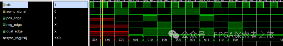
Figure 1. Simulation waveform of synchronized edge detection
It can be seen that the rising edge (pos_edge) is detected at (sync_reg[2] && !sync_reg[1]); the falling edge (pos_edge) is detected at (!sync_reg[2] && sync_reg[1]); the dual edge (dual_edge) is detected at (sync_reg[2] ^ sync_reg[1]).
Note: The detected edges are the results after eliminating metastability,which is equivalent to detecting different edges after sampling the async_signal signal twice and then using the three-clock method in the first part; the results from both methods are essentially the same.
3. Pulse Width Expansion Edge Detection(Adjustable Width Edge Detection)
When the edge pulse needs to last for multiple clock cycles:
module wide_posedge_detect(
input clk,
input signal,
input [7:0] width,
output pos_edge
);
reg signal_delay;
reg [7:0] counter;
always @(posedge clk) begin
signal_delay <= signal;
if (signal & ~signal_delay) begin // Detected rising edge
counter <= width;
end else if (counter != 0) begin
counter <= counter – 1;
end
end
assign pos_edge = (counter != 0);
endmodule
Working Principle:
After detecting the edge, the counter is started;
the output remains high during the countdown of the counter;
the output goes low after the counter reaches zero.
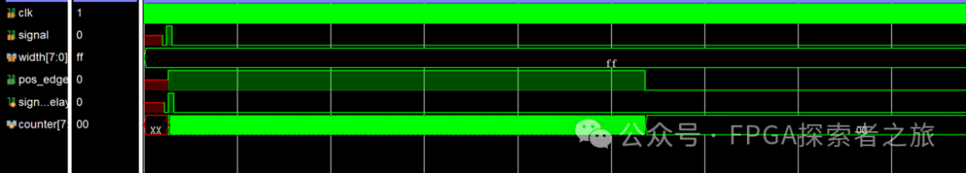
Figure 2. Simulation waveform of adjustable width edge detection
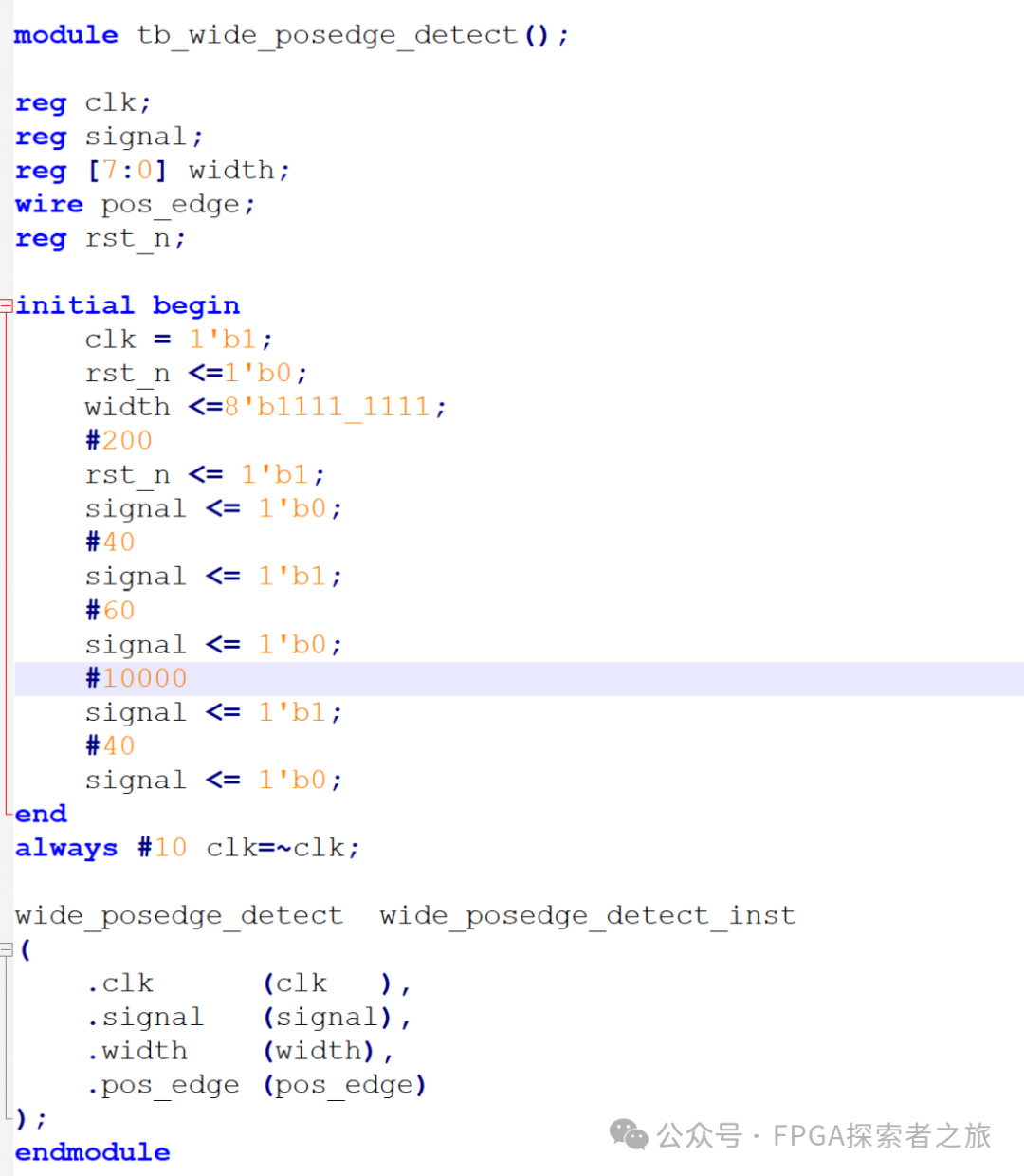
Figure 3. Testbench code for adjustable width edge detection