1 Introduction
To understand how microcontrollers execute programs, it is essential to first comprehend the components of a microcontroller. This article uses the 80C51 microcontroller as an example to explain how programs run within a microcontroller.
2 Components of a Microcontroller
The internal hardware structure of the 8051 microcontroller includes:
- Central Processing Unit (CPU): This is the core component of the microcontroller, determining its primary functional characteristics, consisting of an arithmetic logic unit and a control unit.
- Memory: The 8051 microcontroller adopts a Harvard architecture, storing programs and data in two separate memory units, one called program memory and the other data memory. Physically, there are four independent storage spaces: on-chip ROM, off-chip ROM, on-chip RAM, and off-chip RAM.
- Timer/Counter (T/C): The 8051 microcontroller has two 16-bit timer/counters, each of which can be set to either counting mode or timing mode, controlling the computer based on the timing count results.
- Parallel I/O Ports: The 8051 has four 8-bit parallel I/O interfaces (P0 to P3) for parallel data input and output.
- Serial Port: The 8051 microcontroller features a full-duplex serial port for serial communication between microcontrollers or other devices.
- Interrupt Control System: The 8051 has a total of five interrupt sources, categorized into high and low priority levels. It can receive external interrupt requests, timer/counter requests, and serial port requests, commonly used for real-time control, automatic fault handling, data transfer between the computer and peripherals, and human-machine dialogue.
3 Microcontroller Startup Process
The startup process of a microcontroller begins after power is applied, running the inherent program within the chip (this program is inaccessible and unmodifiable by the user), known as the startup code. Once the startup code establishes the runtime environment, it reads the status of the serial port, which is used for downloading programs, to determine if the user is preparing to download a program.If so, it downloads the user program to the specified address as requested. If not, it jumps to the entry point of the already downloaded user program, transferring control to the user program. If it is a new chip that has not yet been programmed, it remains in a loop reading the serial port status.The startup code is typically burned into flash memory and is executed immediately upon power-up, running before any user C code. After power-up, the ARM processor is in ARM state, operating in management mode, with all system interrupts disabled, and the program counter (PC) fetches instructions from address 0.An executable image file must have an entry point, and the entry address of an image file that can be placed at the start of ROM must also be set to 0. In assembly language, one can define a program’s entry point. When there are multiple entry points in a project, the linker must use -entry to specify the program’s entry point.If the user-created program includes a main function, there will also be an entry point corresponding to the C library initialization code. Overall, the startup code primarily accomplishes two tasks: initializing the execution environment, such as the interrupt vector table, stack, I/O, etc.; and initializing the C library and user application.In the first phase, the startup code process can be described as follows:
- Establishing the interrupt vector table;
- Initializing memory;
- Initializing the stack register;
- Initializing I/O and other necessary devices;
- Changing the processor state as needed.
Devices with systems, like PCs, operate similarly upon power-up, except they read the BIOS, which completes many initialization operations before calling the system initialization function, transferring control to the operating system, thus booting Windows or Linux.If we consider the operating system as a large bare-metal program running on the processor (since the operating system runs directly on the CPU), the startup of the operating system resembles that of an MCU program. The former has a large initialization program that completes complex initializations, while the latter has a short assembly code that performs simple initializations.What about the startup of programs on the system? They are determined by the system. In Linux, when entering ./p in the shell, it first checks if it is a built-in shell command; if not, the shell assumes it is an executable file (usually in ELF format on Linux), then calls related functions to copy the contents of the p file from the hard disk to memory (DDR RAM) and establishes its runtime environment (including memory mapping, virtual memory, linking, loading, and other processes) in preparation for execution.From the above, it is clear that the startup of programs on microcontrollers differs significantly from that of programs running on systems. If we abstract the actions before calling main as initialization, the program startup can be simplified to: establishing the runtime environment + calling the main function, thus the execution differences are not substantial.This is because the programs running on microcontrollers (bare-metal programs) operate at the same level as the operating system. The past confusion regarding the differences between programs on microcontrollers and those on PCs stemmed from a lack of understanding of this point.
4 Program Execution
Regarding program execution, the confusion about where instructions and data are read from arose from not clarifying the differences between system programs and bare-metal programs.The execution process of a program in a microcontroller consists of fetching instructions, decoding instructions, and executing instructions:
- The task of fetching instructions is to read the current instruction from program memory based on the value in the program counter (PC) and send it to the instruction register.
- The task of the instruction decoding phase is to extract the opcode from the instruction register, decode it, and analyze its nature. If the instruction requires operands, it searches for the operand addresses.
- The process of executing a program is essentially a repetition of the above operations for each instruction until a halt instruction is encountered, at which point it waits for the next instruction.
Although in the “Principles of Microcomputers” course, it is understood that programs run by reading instructions and data from memory for execution and writing back, the microcontroller has only a few kilobytes of RAM, while flash memory typically has tens of kilobytes or even 1 megabyte. At this point, are instructions and data both in memory?Here, memory refers only to RAM, as we commonly refer to memory on PCs as DDR RAM memory, leading to the assumption that microcontrollers operate similarly without realizing that both RAM and Flash are types of memory.This is not possible because the instructor only mentioned memory, but on PCs, memory generally refers to DDR RAM, not the hard disk, which is where data is stored. Thus, when making comparisons, one can become confused, thinking that the microcontroller’s RAM corresponds to DDR RAM, and whether Flash corresponds to the hard disk. In CSAPP, it became clear that the reason programs on PCs reside in DDR RAM is due to speed considerations.The speed of hard disks is too slow; even the upcoming SSDs are several orders of magnitude slower than DDR RAM, necessitating copying to DDR RAM. At this point, a program’s code and data are stored contiguously, with the code segment being read-only and the data segment being read-write (this is determined by the operating system’s memory management mechanism).During execution, they are copied to faster SRAM for improved execution speed. For microcontrollers, however, with operating frequencies in the range of a few MHz to tens of MHz, the difference between reading from Flash and RAM may not be significant enough to become a bottleneck in program execution. In contrast, for PCs, the speed of Flash is too slow, and DDR RAM is also relatively slow, even SRAM is considerably slower, thus increasing the operating frequency does not enhance program execution speed. Consequently, the fastest CPU operating frequency peaked around 2003, marking a bottleneck.
5 Example
Upon startup, the program counter (PC) is set to 0000H. The microcontroller then automatically enters the program execution process under the influence of the timing circuit. The execution process is essentially a loop of fetching instructions (retrieving pre-stored instructions from memory) and executing instructions (analyzing and executing instructions).For example, executing the instruction: MOV A,#0E0H, whose machine code is 74H E0H, functions to load the operand E0H into the accumulator. The 0000H cell contains 74H, and the 0001H cell contains E0H. When the microcontroller begins operation, it first enters the fetch phase, in the following order:
- The content of the program counter (currently 0000H) is sent to the address register;
- The content of the program counter is automatically incremented (to 0001H);
- The content of the address register (0000H) is sent to memory via the internal address bus, selecting the memory cell at address 0000H;
- The CPU activates the read control line;
- Under the read command, the content of the selected memory cell (which should be 74H at this point) is sent to the internal data bus, and since this is the fetch phase, this content is sent to the instruction register via the data bus.
6 Multithreaded Program Execution
To improve CPU utilization, consider this: since we cannot reduce the execution time of a segment of code, we can execute more programs in the same time frame. One core can execute one program, and two cores can execute two programs, making multi-core CPUs the mainstream today.Thus, bare-metal program instructions are stored in Flash (Flash memory), while data is placed in RAM (as Flash has a limited number of write cycles and its speed is still much lower than RAM). More broadly, in microcontrollers, RAM stores the data segment, BSS segment, and stack segment; ROM (EPROM, EEPROM, Flash, and other non-volatile storage devices) stores code and read-only data segments.Essentially, this is similar to how programs are stored in RAM on PCs, where the operating system defines read and write permissions, while in microcontrollers, different storage devices distinguish between read and write capabilities.Of course, modern Flash is read-write capable. If Flash had no write cycle limitations and its speed were comparable to RAM, could microcontrollers rely solely on Flash (equivalent to DDR RAM on PCs)? This would lower costs compared to having both RAM and Flash, making it more economical for manufacturers.
7 Data Storage and Retrieval
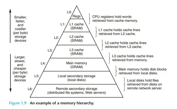
Regarding the storage and retrieval of instructions and data during program execution on microcontrollers, the understanding is as follows:After programming a microcontroller, the code segment, data segment, BSS segment, and rodata segment are all stored in Flash. When the microcontroller is powered on, the initialization assembly code copies the data segment and BSS segment to RAM and establishes the stack, beginning the call to the main function of the program.Subsequently, there is a distinction between program memory and data memory, where instructions are read from Flash (the instruction memory, code memory) and data is read from and written to RAM. The significance of RAM lies in its faster speed.Whether in microcontrollers or PCs, the hierarchy of memory storage is consistent, with speed factors and cost limitations leading to progressively faster storage levels with higher costs. Understanding this is essentially understanding the memory hierarchy.