QA&
Question: A Beginner’s Guide to Understanding Industrial Control Systems with Arduino Micro PLCs
 Arduino Opta Micro PLCArduino Opta® is a safe and easy-to-use micro PLC with industrial IoT capabilities. It can expand industrial and building automation projects while fully leveraging the advantages of the Arduino ecosystem. The Arduino Opta is not a toy. It is designed to live and work in industrial environments. It is fully capable of controlling large machinery that could potentially harm people. Similarly, it can be installed in cabinets next to hazardous high-voltage three-phase power sources to control large motor starters.Physical Description of Opta PLC OutputsThe Arduino Opta PLC has four relay-based outputs. According to thespecifications, each relay can handle 10 A at 250 VAC. As a beginner, it is recommended not to approach these design maximum specifications. Instead, it is advisable to conservatively output no more than 1 A at 24 VDC. If additional current or voltage is needed, we should consider using intermediate relays. Again, this is a beginner’s guide. Just because the Opta can do it, does not mean we should. At least not at first, until we have experience building systems.
Technical Tip:
Intermediate relays are control relays located in between. They are installed between the PLC and larger contactors. For example, suppose the PLC is used to control a large three-phase motor. Let’s further assume the motor starter has a 120 VAC coil. The PLC will connect to drive the intermediate relay’s 24 VDC coil. Then, the contacts of this intermediate relay are used to power the 120 VAC coil of the motor starter. This configuration increases the capabilities of the PLC. It also serves a safety function by isolating the wiring. The intermediate relay separates the 24 VDC control signal from the 120 VAC wiring.
Safe Schematic Using 24 VDC
The good news is that 24 VDC systems are very common, with many compatible components available. This includes pneumatic actuators, panel lights, various control relays, and contactors for large loads. This is good news for beginners as we will be experimenting with standardized industrial components that are both safe and economical.
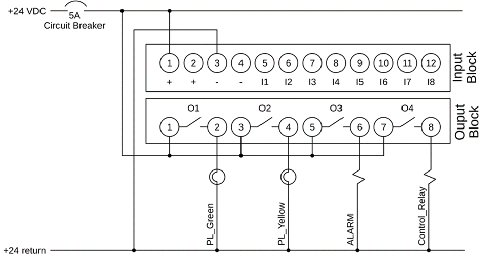
This schematic illustrates a method of connecting the Arduino Opta to various 24 VDC loads. Note that a 5 A circuit breaker provides a degree of protection. While this type of circuit breaker is typically associated with higher voltage AC circuits, it is also applicable for low-voltage DC operations. Please note that depending on the nature of the DC power supply you choose, this circuit breaker may or may not be necessary. Some power supplies have overcurrent protection, while others have fuse protection. Some power supplies have no protection, which could lead to damage if wired incorrectly.
Technical Tip:
This wiring diagram uses daisy chaining. This is achieved through the dual wire terminals described in this article.
The next noteworthy item in this schematic is the daisy chain connection of the output relays, where PLC pins 1, 3, 5, and 7 provide 24 VDC. Then, pins 2, 4, 6, or 8 can power various loads, with the other end of each load connected to the 24 VDC return circuit. This is referred to in the industry as a “source configuration”. In this setup, the PLC is the source of positive voltage.

More PLC Design Technology Information can be found in the following:1. A Beginner’s Guide to Connecting Digital Inputs to Arduino Opta PLC2. Mastering Non-Blocking Arduino Delays by Adapting PLC Technology3. Introduction to Arduino Plug-and-Play Kits4. Initial Steps for DIN Rail Hardware5. Educational Guide to Selecting Industrial Components6. Exploring Open Source Hardware from the Perspective of Industrial Control and AutomationFinally, if you enjoyed this article, feel free to share it with more friends! Remember to give it a thumbs up!!
Tip Click on the menu design support: Engineer’s Tips, for more engineering tips


↙ Click on “Read the original text” below for more
If you found this article helpful, clickRecommend to let more people see it!