1 Robotic Arm System Structure
The robotic arm system includes a computer control terminal, a visual positioning module, a USB to CAN module, and an electric joint module, as shown in Figure 1.
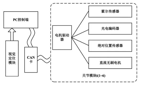
Figure 1: Robotic Arm System Structure
The visual positioning module provides a description of the end effector’s position in Cartesian space. This paper mainly focuses on the research of the control system, so the visual positioning module will not be introduced. The computer control terminal uses the Advantech IPC-610H series to run the control software; the CAN card used is the Ixxat USB CAN COMPACT module, which solves the communication from the control terminal to the execution terminal. The electric joint module includes Elmo motor servo drivers, Maxon brushless DC motors, incremental photoelectric encoders, absolute position sensors, and Hall sensors. The Elmo motor servo control can accurately achieve control of the motor position loop, speed loop, and current loop with the assistance of sensors. Therefore, the focus of this paper is on the configuration of the CANopen communication protocol from the control terminal to the execution terminal, as well as the design and verification of the upper-level control algorithm for the robotic arm.
2 Configuration of CANopen Protocol
The control of the robotic arm ultimately boils down to the control of the motor. The CiA draft standard Proposal 402 is specifically designed for motion control and defines all parameters used for motor control in the CANopen object dictionary, including encoder position, motor speed, motor acceleration, and motor pole pairs. In the CANopen protocol, PDO (Process Data Object) communication is used for high-speed data transmission, with each message capable of transmitting up to 8 bytes of valid data, suitable for the transmission of motor control quantities, meeting the real-time requirements of robotic arm control. PDO communication does not specify a communication protocol; designers map the used object dictionary to the PDO unit, a process called PDO Mapping. The configuration of the CANopen protocol mainly focuses on the configuration of PDO communication, while other aspects are standardized as per the protocol.
PDO structure units are shown in Table 1.
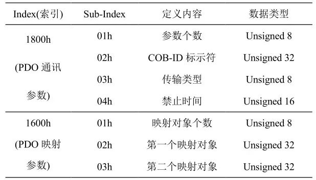
Each PDO unit is described by 2 objects in the object dictionary: PDO communication parameters, which include which COB-ID will be used by the PDO, transmission type, inhibit time, and timer cycle; and PDO mapping parameters, which include a list of objects in the object dictionary that are mapped to the PDO, including their data lengths, etc. Taking TPDO1 as an example, the PDO configuration is shown in Table 2.
Table 2: PDO Configuration
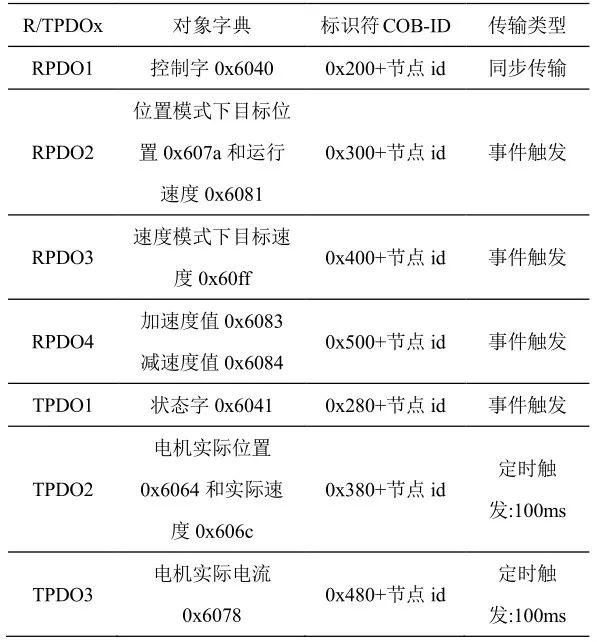
Common motor control quantities used in the joint space of the robotic arm include target motor speed, motor acceleration, motor deceleration, and target motor position. At the same time, the control terminal continuously monitors the motor’s motion state values, including motor position feedback, motor speed feedback, and motor current feedback. The Elmo motor driver can receive and send 4 groups of PDOs, namely RPDO1~RPDO4 and TPDO1~TPDO4. In this study, the above control quantities and feedback quantities are mapped to the corresponding PDO units in the CANopen protocol, as shown in Table 2, where the node ID in the table represents the node number of each joint device of the robotic arm in the CAN network.
After the CAN bus is started, it is necessary to configure the PDO for each joint motor driver. Once the configuration is complete, the control terminal uses the RPDO1 message to control the motor driver state, the RPDO2 message to send the target position and running speed commands in position mode, the RPDO3 message to send the target speed command in speed mode, and the RPDO4 message to send the motor acceleration and deceleration commands. Through the TPDO message, the control terminal periodically receives feedback on the motor status, current position, current speed, and current feedback. The PDO configuration lays the foundation for the control of the robotic arm system in joint space and solves the communication problem from the control terminal to the execution terminal.
For further content, please pay attention to the next update on the WeChat public account.
(Original text reproduced from: “Research on Control System of Robotic Arm Based on CANopen”, Authors: Wang Yaonan, Gao Xiaolong, School of Electrical and Information Engineering, Hunan University)